Device for the measurement of coating thicknesses by means of microwaves

a technology of coating thickness and measurement device, which is applied in the direction of measurement device, resistance/reactance/impedence, instruments, etc., can solve the problems of inherently limited measurement accuracy, inability to measure thickness units, and substrates with polymer coatings that must feature a really high electrical conductivity. , to achieve the effect of minimising the influence of materials

Active Publication Date: 2011-03-17
AIRBUS OPERATIONS GMBH
View PDF13 Cites 10 Cited by
  • Summary
  • Abstract
  • Description
  • Claims
  • Application Information

AI Technical Summary

Benefits of technology

[0023]As a result of the passage of current through the at least one web that by this means ensues, the latter forms an inductance, which in interaction with the series capacitance formed by the separation distance further minimises the influence of the material on the coating thickness measurement. Four webs are preferably provided between the electrode pin centrally arranged in the outer conductor and the outer conductor; in each case these are arranged displaced by 90° from each other. The webs are arranged in the form of spokes, directed radially outwards from the electrode pin and extend in each case from the base of the electrode across a circular opening of the probe flange. The webs can, for example, feature a quadratic cross-sectional geometry with an edge length of 0.5 mm.

Problems solved by technology

Such coating thickness measurement units do not allow on the one hand a non-destructive measurement and on the other hand the measurement accuracy that can be achieved is inherently limited in principle, in particular in the case of low material thicknesses of the polymer coating.
While measurement units of this type do allow a non-destructive measurement with a sufficiently high accuracy after calibration has taken place, they have the disadvantage that the substrate with the polymer coating must feature a really high electrical conductivity.
Accordingly these units are only suitable to a limited extent for the measurement of the material thickness of a polymer coating on a substrate formed from a composite material, which as a rule has a relatively poor electrical conductivity, as, for example, in the case of a carbon fibre-reinforced epoxy resin.
However this coating thickness measurement unit of prior art only allows a measurement of the thickness of a coating located on a purely metallic base material.

Method used


Image

  • Device for the measurement of coating thicknesses by means of microwaves
  • Device for the measurement of coating thicknesses by means of microwaves
  • Device for the measurement of coating thicknesses by means of microwaves

Examples


Embodiment Construction

[0029]In the drawings the same structural elements have in each case the same reference numbers.

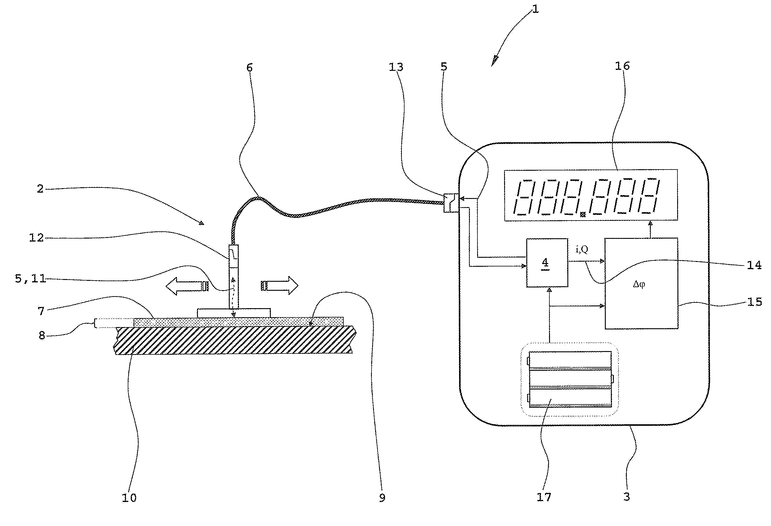
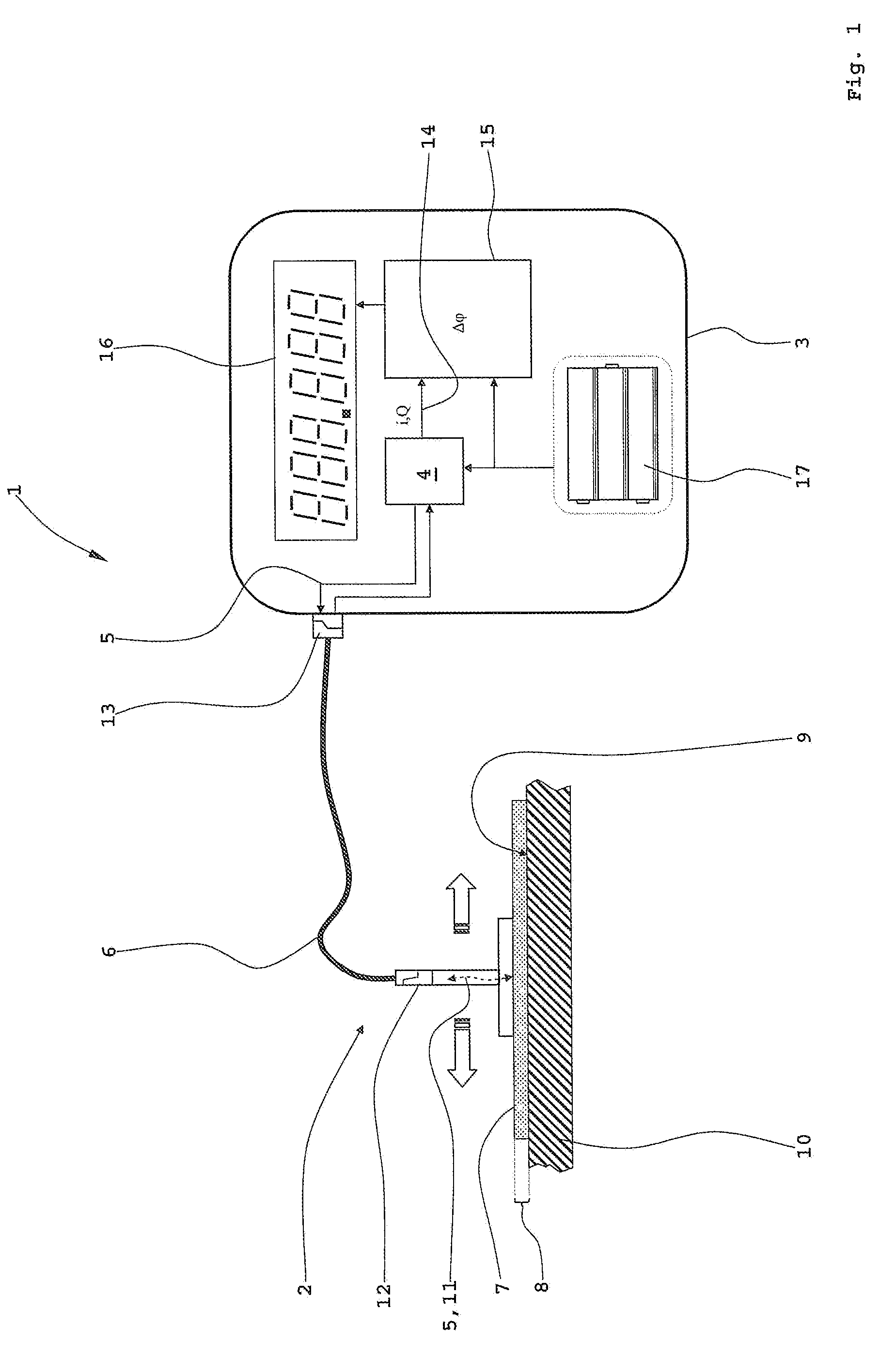
[0030]FIG. 1 illustrates a schematic representation of the device according to the invention for the measurement of coating thicknesses.

[0031]A device 1 comprises amongst other items a mobile probe 2 as well as a housing 3, whose spatial dimensions are selected such that it can preferably be held by a user in one hand. In the housing 3 is located, amongst other items, a combined transmitter / receiver module 4 for microwave radiation. The microwave radiation 5 emitted from the transmitter / receiver module 4 is fed via a coaxial cable 6 to the probe 2. There the emitted microwave radiation 5 penetrates a polymer coating 7, whose material thickness or coating thickness 8 is to be determined, is reflected back in the region of a surface 9 of a substrate, and finally returns as reflected microwave radiation 11 to the combined transmitter / receiver module 4. The highly flexible coaxial cable 6 is ...


PUM


Abstract

A device for measurement of a thickness of a coating applied to a substrate includes a transmitter/receiver module configured to transmit and receive microwave radiation; a computing unit; and a probe having a flange and an inner and an outer conductor, wherein the outer conductor coaxially surrounds the inner conductor, and wherein the inner conductor includes at least one thickened section.

Description

[0001]Priority is claimed to German Utility Patent Application No. DE 20 2009 012 483.5, filed Sep. 14, 2009, the entire disclosure of which is incorporated by reference herein.[0002]The invention relates to a device for the measurement of coating thicknesses by means of microwave radiation, in particular for the thickness measurement of at least one polymer coating, which is applied to a substrate, in particular one formed with an electrically conducting composite material, with a transmitter / receiver module, a computing unit, and with a probe with a flange. In addition the invention relates to a further form of embodiment of the device.BACKGROUND[0003]In modern aircraft construction it is usual, for visually aesthetic reasons amongst others, as well as for the prevention of corrosion effects, to coat the primary structure of aircraft with at least one polymer layer, for example in the form of paintwork. The polymer layer or layers can fulfil a large number of different functions. ...

Claims


Application Information

Patent Timeline
Patent Type & Authority Applications(United States)
IPC IPC(8): G01R27/04
CPCG01B15/02
Inventor BRANDT, CARSTENBISLE, WOLFGANGDANNEMANN, JOERGHINKEN, JOHANNBELLER, THOMAS
Owner AIRBUS OPERATIONS GMBH
Why Eureka
Try Eureka