Delay line interferometers

a technology of delay line and interferometer, which is applied in the direction of measuring devices, instruments, polarising elements, etc., can solve problems such as optical coatings, and achieve the effect of reducing costs and simplifying manufactur

Active Publication Date: 2011-03-17
II VI DELAWARE INC
View PDF8 Cites 9 Cited by
  • Summary
  • Abstract
  • Description
  • Claims
  • Application Information

AI Technical Summary

Benefits of technology

[0004]We have developed delay line interferometer designs using combinations of basic optical components that are expected to simplify manufacture and reduce costs while still prov

Problems solved by technology

Delay line interferometers for DPSK systems are high performance optical devices

Method used


Image

  • Delay line interferometers
  • Delay line interferometers
  • Delay line interferometers

Examples


Embodiment Construction

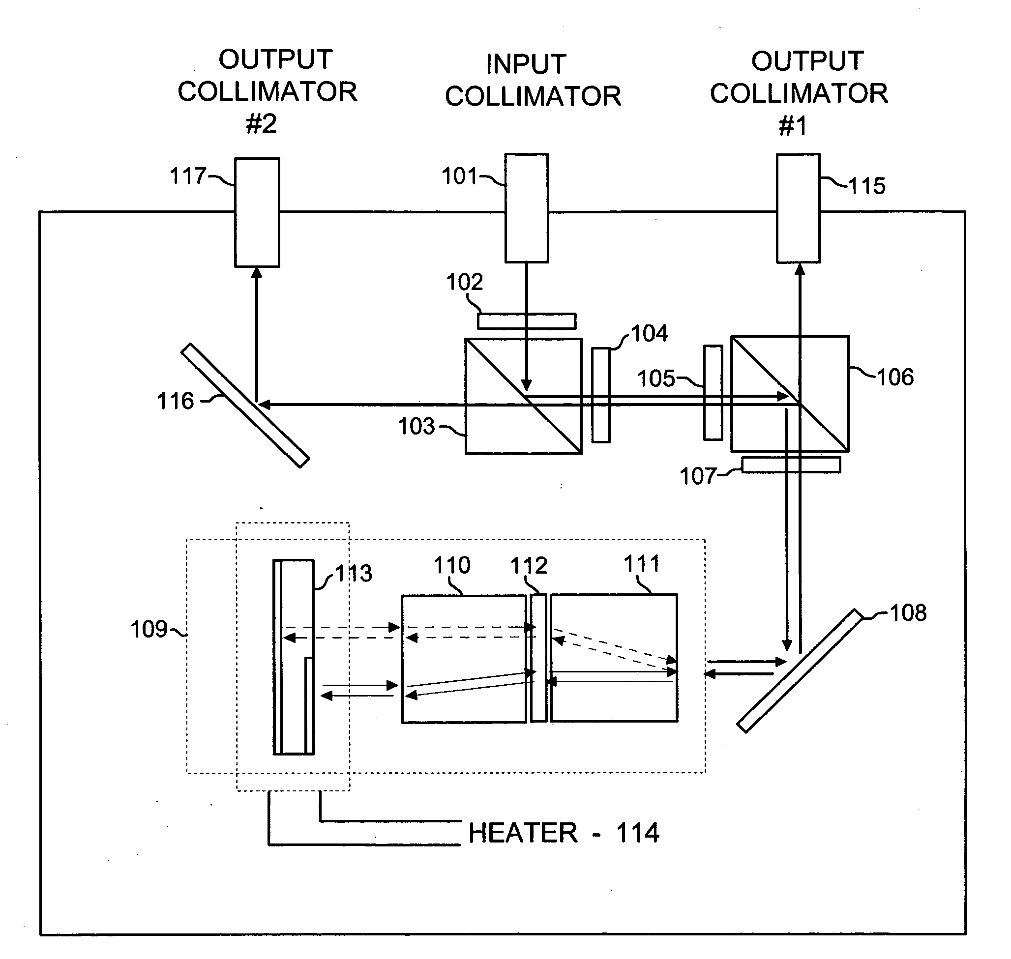
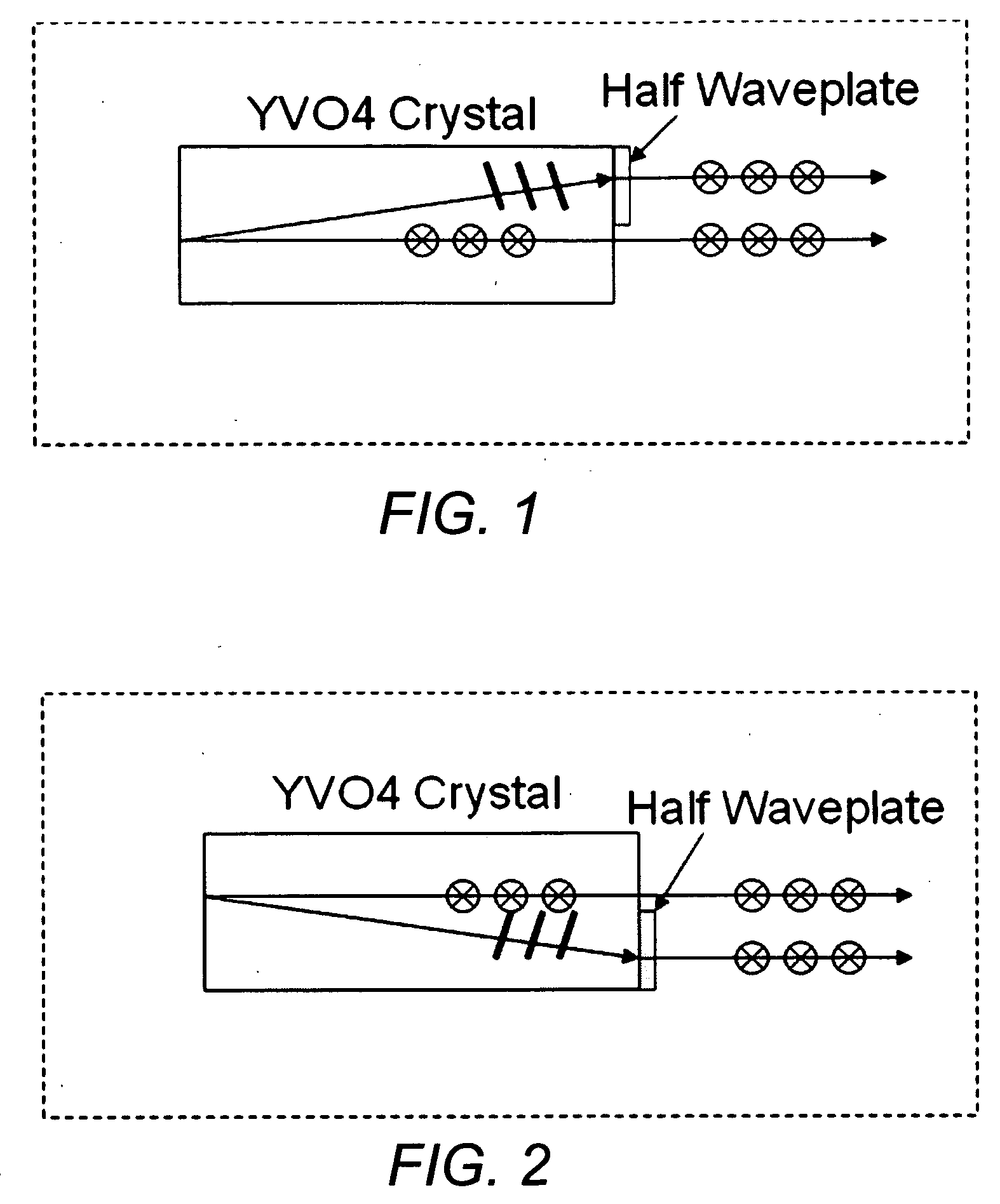
[0009]With reference to FIG. 1, a side view of a subassembly of a birefringent crystal, in this illustration a yttrium vanadate (YVO4) crystal, with a half waveplate (see FIG. 4) attached as shown. In this arrangement an input optical beam with random polarization state is converted into two parallel beams with the same linear polarization state. The polarization direction, in this illustration, is perpendicular to the drawing. This subassembly will be used as an input collimator for the delay line interferometer of the invention.

[0010]FIG. 2 shows a subassembly for an output collimator used in the delay line interferometer of the invention. It is similar to the subassembly of FIG. 1 except that it is inverted on a horizontal axis. In a device using these subassemblies paired for input and output, polarization mode dispersion (PMD) may be minimized.

[0011]The yttrium orthovanadate birefringent crystal in FIGS. 1 and 2 is intended as an example only of a variety of birefringent materi...


PUM


Abstract

The specification describes delay line interferometer designs using combinations of basic optical components that are expected to simplify manufacture and reduce costs while still providing precision optical performance. The main operative components of these designs are polarization beam splitters, birefringent crystals, optical delay components, and waveplates. Temperature controllers may be provided for adjusting the delay of the optical delay components.

Description

FIELD OF THE INVENTION[0001]The invention relates to improvements in optical delay devices and more particularly to optical delay interferometers adapted for differential phase shift keying demodulation systems.BACKGROUND OF THE INVENTION[0002]Delay line interferometers are typically Mach-Zehnder type or Michelson type interferometers based on multiple beam interference in which one beam is time-delayed to another by a desired interval. As applied to Differential Phase-Shift Keying (DPSK), demodulation delay line interferometers convert a phase-keyed signal into an amplitude-keyed signal. In this application, an incoming DPSK optical signal is split into two equal-intensity beams in two arms of a interferometer, wherein one beam is delayed by a given optical path difference corresponding to a one bit delay in the DPSK scheme. The beams are recombined producing constructive or destructive interference in the time domain for each bit. The resultant interference intensity is the intens...

Claims


Application Information

Patent Timeline
IPC IPC(8): G02B27/28
CPCG02B27/283
Inventor CAI, MINGWANG, RUIBO
Owner II VI DELAWARE INC
Why Eureka
Try Eureka