Biopsy device with acoustic element

a biopsy device and acoustic element technology, applied in medical science, surgery, vaccination/ovulation diagnostics, etc., can solve the problems of inability to know for certain whether the biopsy is taken from the correct position inside the tissue that should be analysed, the guidance method is far from optimal, and the biopsy is not taken from the correct position inside the tissue. the effect of acoustic element, facilitating needle integration, and reducing the thickness of the transducer

Inactive Publication Date: 2011-03-17
KONINKLIJKE PHILIPS ELECTRONICS NV
View PDF17 Cites 64 Cited by
  • Summary
  • Abstract
  • Description
  • Claims
  • Application Information

AI Technical Summary

Benefits of technology

[0044]It is an advantage of this configuration that there may be always a reference surface at a known distance which will reflect the ultrasound, therefore the first echo recorded can give the acoustic velocity in the tissue. Moreover, it may be possible to measure continuously the acoustic properties (e.g. velocity, attenuation) of the tissue layer which is momentarily penetrated.
[0045]Such a configuration may allow to use higher ultrasound frequencies because the signal sent out by the transducer element has to penetrate just a small distance (higher frequencies lead to stronger absorption), this means that the thickness of the transducer may be decreased, facilitating the integration into the needle.
[0046]For example, for a 1 MHz piezoelectric transducer element from PVDF (polyvinylidenefluoride) the minimum thickness of the disk is around 750 micrometer without backing, which means the thickness of the complete transducer is more than 1 mm. For PZT (plumbum zirconate titanate) based compounds the compressional wave velocity is higher. In case of a PVDF transducer at 15 MHz the minimum thickness of the disc is about 50 micrometer, which enables its integration easily into the needle. The same transducer from PZT needs a 140 micron thick disc.

Problems solved by technology

Although helpful, these methods of guidance are far from optimal.
There are two major problems directly related to the biopsy: The resolution is limited and, furthermore, these imaging modalities can in most cases not discriminate between benign and malignant tissue.
As a result, it is not known for certain whether the biopsy is taken from the correct position inside the tissue that should be analysed.
Physicians take biopsies almost blindly and even if after inspection of the tissue no cancer cells are detected, they do not know for certain whether they did not simply miss the right spot.
Since each biopsy causes a scarf and possibly complications, this is not a preferred solution.

Method used


Image

  • Biopsy device with acoustic element
  • Biopsy device with acoustic element
  • Biopsy device with acoustic element

Examples


Embodiment Construction

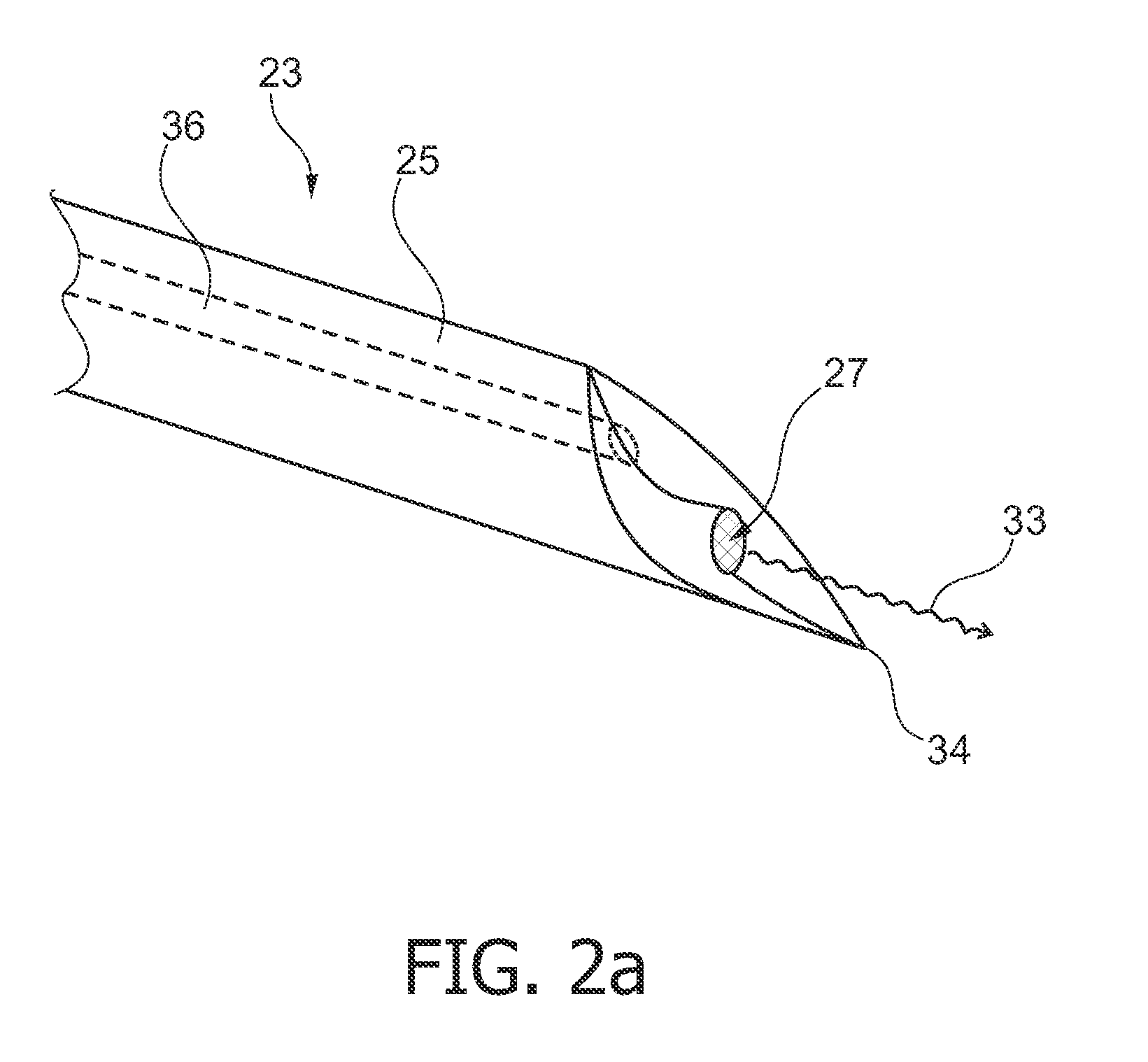
[0096]As illustrated in FIG. 2a and FIG. 2b, the elongated shaft 25 of the tip portion 23 of the biopsy device according to the invention comprises a bore 36 which may include e.g. a conventional needle such as a hollow metal needle for biopsy procedures, around which the material of the shaft 25 may be located.

[0097]The shaft 25 of the biopsy device comprises a distal end 34, which is peripherally arranged at the distal region of the shaft. The shaft 25 of the biopsy device further comprises a planar front surface 32 which may be centrally arranged relative to the shaft 25. The planar front surface 32 may be located on a pin 31, which is arranged on the shaft 25. The pin 31 may be a part, e.g. elevation of the shaft or a separate object, which is connected to the shaft.

[0098]A transducer element 27 for emitting and / or receiving ultrasound waves is arranged on the planar front surface 32. The wire 39 of the transducer element 27 may be embedded in the shaft 25.

[0099]The transducer e...


PUM


Abstract

The invention relates to a biopsy device, particularly a biopsy device comprising a shaft with a transducer element for providing information about acoustic properties of a material to be analysed, a system of positioning a biopsy device and a method for positioning a biopsy device. The biopsy device may be adapted to take biopsies of different regions of the 5 human body for excluding or detecting abnormalities as cancerous lesions. The biopsy device may be used to measure acoustic properties of the material while inserting the tip portion of the biopsy device into the material to be analysed. The biopsy device may further allow measurement based on elastography.

Description

FIELD OF THE INVENTION[0001]The invention generally relates to a biopsy device, particularly a biopsy device for providing information about acoustic properties of a material to be analysed, a system for positioning a biopsy device and a method for positioning a biopsy device.TECHNOLOGICAL BACKGROUND[0002]For a correct diagnosis of cancer, usually biopsies are taken. This can either be done via the lumen of an endoscope or via biopsy needles. For example, needle biopsy is used to take biopsies from the prostate via the rectum. In order to find the correct position for taking the biopsies, various imaging modalities can be used such as X-ray, MRI and ultrasound. In case of prostate cancer, in most cases the needle is guided by an ultrasound probe that is inserted into the rectum.[0003]Although helpful, these methods of guidance are far from optimal. There are two major problems directly related to the biopsy: The resolution is limited and, furthermore, these imaging modalities can in...

Claims


Application Information

Patent Timeline
Patent Type & Authority Applications(United States)
IPC IPC(8): A61B10/00
CPCA61B8/12A61B8/445A61B10/0241A61B2019/5276A61B2017/00057A61B2017/00106A61B2017/3413A61B17/3403A61B2090/378
Inventor KUIPER, STEINHENDRIKS, BERNARDUS HENDRIKUS WILHELMUSKLEE, MAREIKEDELADI, SZABOLCSMARESCE, DAVID
Owner KONINKLIJKE PHILIPS ELECTRONICS NV
Why Eureka
Try Eureka