
Charged particle beam drawing apparatus and proximity effect correction method thereof

Active Publication Date: 2011-03-24
NUFLARE TECH INC
View PDF0 Cites 27 Cited by
  • Summary
  • Abstract
  • Description
  • Claims
  • Application Information

AI Technical Summary

Benefits of technology

[0014]An object of the present invention is to provide an charged particle beam drawing apparatus and proximity effect correction method thereof, which can easily solve the correction error which appears to the patterns locally in the unit drawing area, such as a chip.
[0015]In detail, the object of the present invention is to provide the charged particle beam drawing apparatus and proximity effect correction method thereof, which can easily solve the correction error which appears to the patterns locally in the unit drawing area, such as critical dimension error caused by resist process (mask process), unknown mechanism.

Problems solved by technology

When patterns are drawn on the workpiece, a correction error can appear to the patterns.
In detail, in one case, a correction error can appear to the patterns throughout the unit drawing area, such as a chip.
However, when a correction error appears to the patterns locally in the unit drawing area, such as a chip, if the proximity effect correction dose D(x) of the charged particle beam in some meshes in the unit drawing area is changed, and if the proximity effect correction dose D(x) of the charged particle beam in another meshes in the unit drawing area is not changed in order to solve the correction error, the condition that the sum (the right side of the equation (1)) is constant in the whole unit drawing area, such as a chip, is not fulfilled.
Accordingly, in the charged particle beam drawing apparatus in the prior art, such as the charged particle beam drawing apparatus described in Japanese Unexamined Patent Publication No. 2003-318077, the proximity effect correction dose D(x) of the charged particle beam in only some meshes in the unit drawing area cannot be changed, therefore, the correction error which appears to the patterns locally in the unit drawing area, such as a chip, cannot be solved.
Consequently, it is not easy to solve the correction error which appears to the patterns locally in the unit drawing area, such as a chip, in the conventional lithography technology.
And large calculation cost is required because calculation time of the computer is enormous.
Accordingly, it is not easy to solve the correction error which appears to the patterns locally in the unit drawing area, such as a chip, in the computer lithography technology.

Method used


Image

  • Charged particle beam drawing apparatus and proximity effect correction method thereof
  • Charged particle beam drawing apparatus and proximity effect correction method thereof
  • Charged particle beam drawing apparatus and proximity effect correction method thereof

Examples


Embodiment Construction

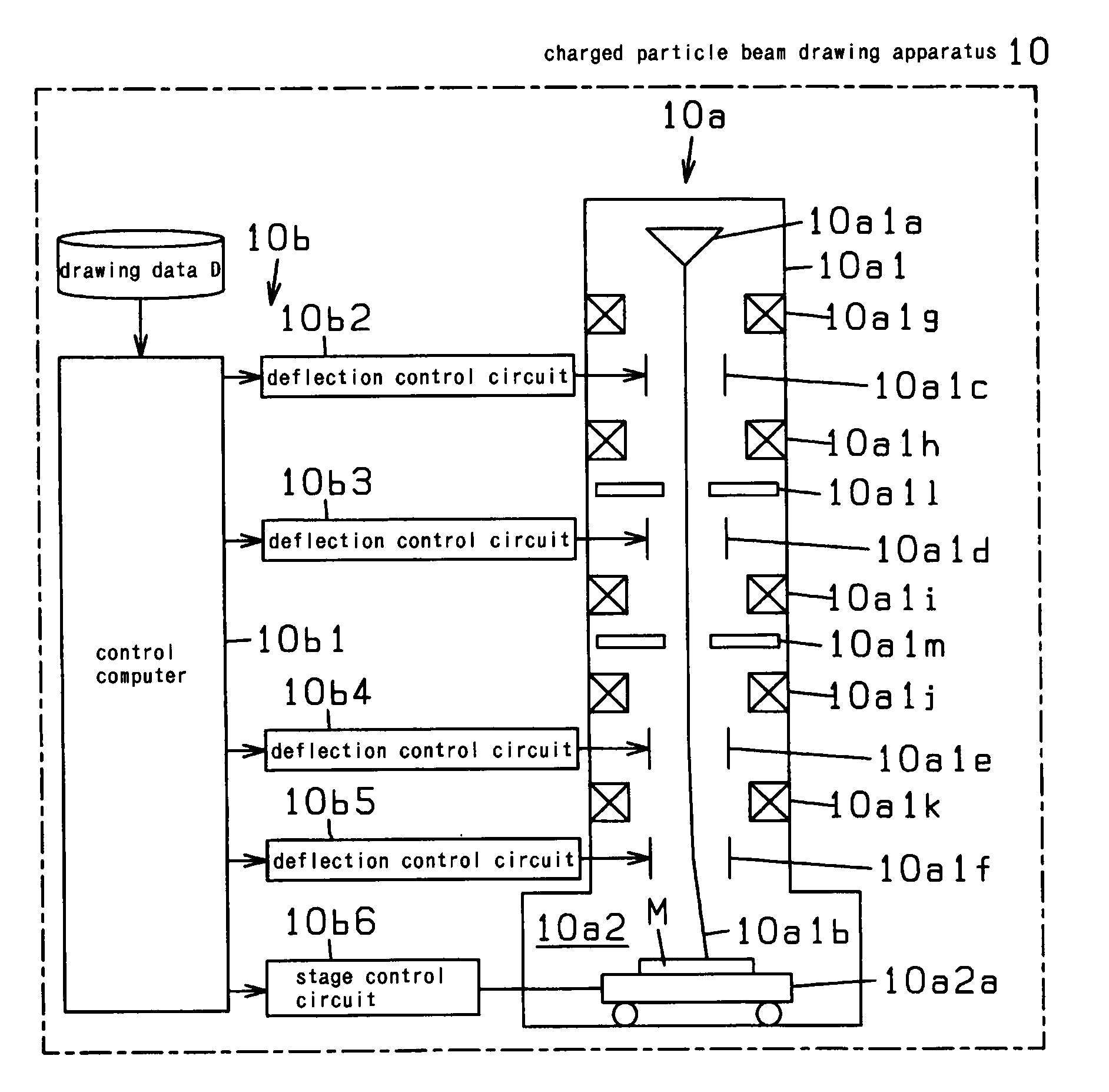
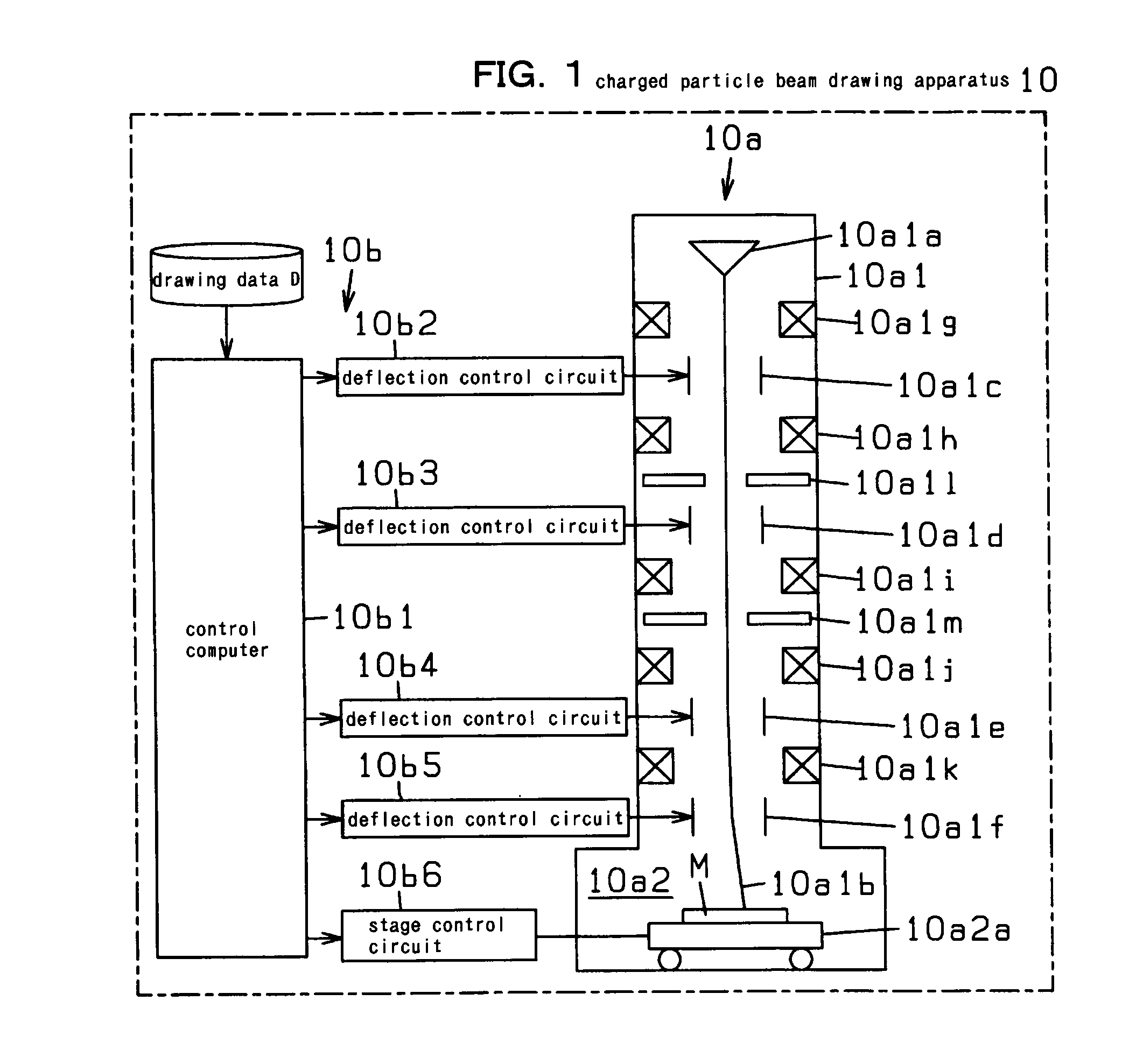
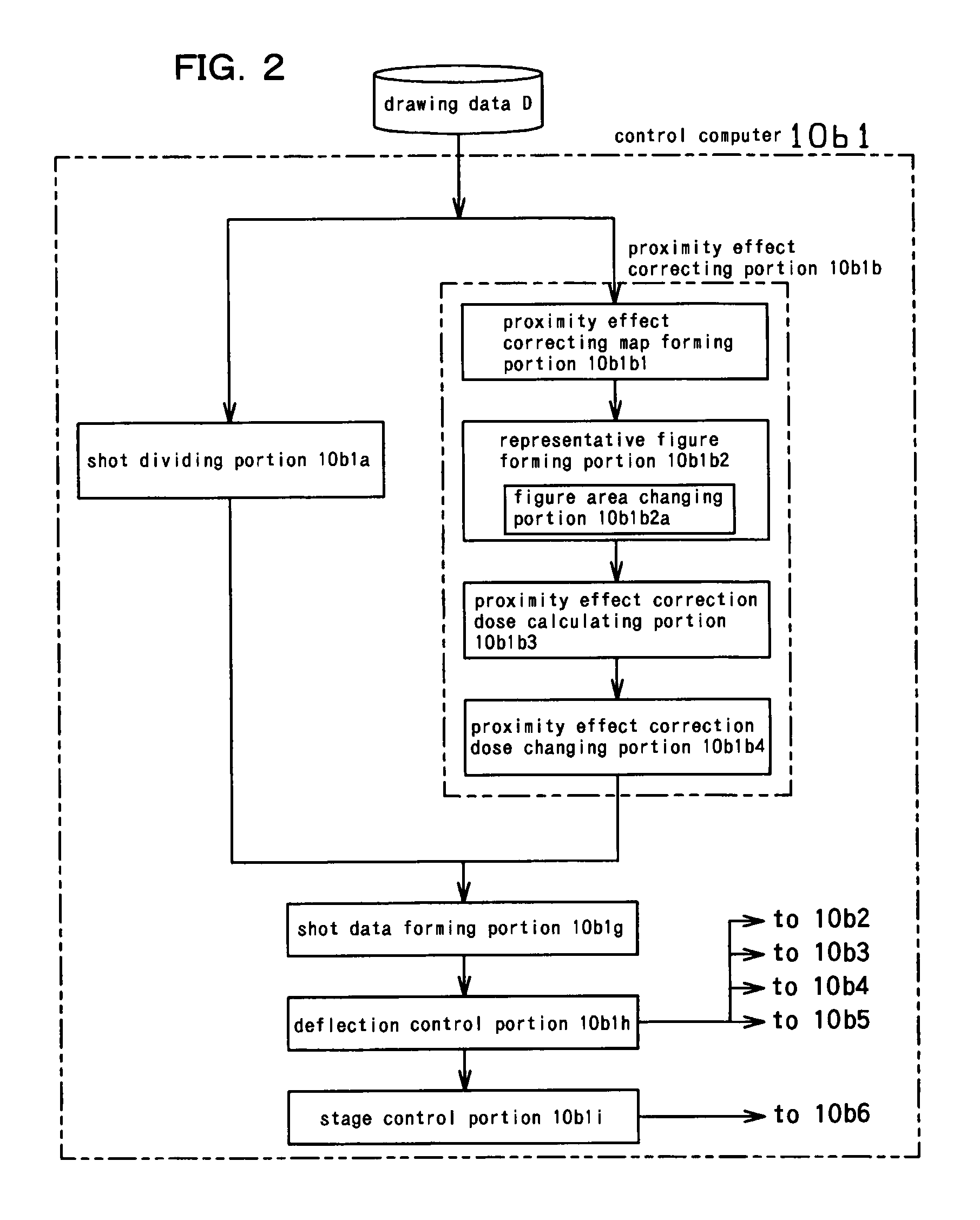
[0036]FIG. 1 is a schematic illustration of a first embodiment of a charged particle beam drawing apparatus 10 according to the present invention. FIG. 2 shows a control computer 10b1 of a control portion 10b of the charged particle beam drawing apparatus 10 of the first embodiment shown in FIG. 1, in detail. As shown in FIG. 1, the charged particle beam drawing apparatus 10 of the first embodiment has a drawing portion 10a for drawing patterns in a drawing area of a workpiece M, such as a mask substrate (reticle) and a wafer, by irradiating the workpiece M with a charged particle beam 10a1b, wherein the workpiece M is formed by applying a resist to an upper surface of the workpiece M.

[0037]In the charged particle beam drawing apparatus 10 of the first embodiment, an electron beam is used as the charged particle beam 10a1b. In the charged particle beam drawing apparatus 10 of a second embodiment, a charged particle beam such as an ion beam, except the electron beam can be used as th...


PUM


Abstract

A charged particle beam drawing apparatus forms a map having meshes, forms representative figures, area of each representative figure in each mesh being equal to gross area of figures in each mesh, and calculates a proximity effect correction dose of the charged particle beam in each mesh on the basis of area of each representative figure in each mesh. If it is necessary to change the proximity effect correction dose of the charged particle beam for drawing at least one pattern corresponding to at least one figure, the charged particle beam drawing apparatus changes area of the at least one figure before the representative figures are formed by a representative figure forming portion, and changes the proximity effect correction dose of the charged particle beam for drawing the at least one pattern corresponding to the at least one figure, calculated by a proximity effect correction dose calculating portion.

Description

CROSS-REFERENCE TO RELATED APPLICATION[0001]This application is based upon and claims the benefit of priority from the prior Japanese Patent Application No. 2009-216469 filed on Sep. 18, 2009 in Japan, the entire contents of which are incorporated herein by reference.BACKGROUND OF THE INVENTION[0002]1. Field of the Invention[0003]The present invention relates to a charged particle beam drawing apparatus and proximity effect correction method thereof, wherein patterns corresponding to figures included in a drawing data are drawn in a drawing area of a workpiece by applying a charged particle beam to the workpiece, wherein a resist is applied to an upper surface of the workpiece.[0004]2. Description of Related Art[0005]As is known in the prior art, in a charged particle beam drawing apparatus, patterns corresponding to figures included in a drawing data (EB data) are drawn in a drawing area of a workpiece, such as a mask substrate (reticle) and a wafer, by applying a charged particle ...

Claims


Application Information

Patent Timeline
IPC IPC(8): G21K5/10G03F7/20G03F1/20G03F1/68H01L21/027
CPCB82Y10/00B82Y40/00H01J2237/31776H01J37/3174H01J2237/31769H01J37/304G03F7/70441G03F7/7055H01L21/0275
Inventor HARA, SHIGEHIROTAMAMUSHI, SHUICHIKAMIKUBO, TAKASHIHIGURASHI, HITOSHISAKAMOTO, SHINJISAKAI, YUSUKEOKAMOTO, YOSHIHIROANPO, AKIHITO
Owner NUFLARE TECH INC
Learn More