

Rotor for permanent magnet rotating machine
a permanent magnet, rotating machine technology, applied in the direction of dynamo-electric machines, electrical apparatus, magnetic circuits, etc., can solve the problems of increasing manufacturing costs, lowering output, and the likelihood of demagnetization, and achieve the effect of high outpu
Active Publication Date: 2011-03-24
SHIN ETSU CHEM IND CO LTD
View PDF11 Cites 21 Cited by
- Summary
- Abstract
- Description
- Claims
- Application Information
AI Technical Summary
Benefits of technology
[0016]An object of the present invention which has been made in view of the above-discussed circumstances is to provide a rotor for use in a permanent magnet rotary machine having a high output and heat resistance.
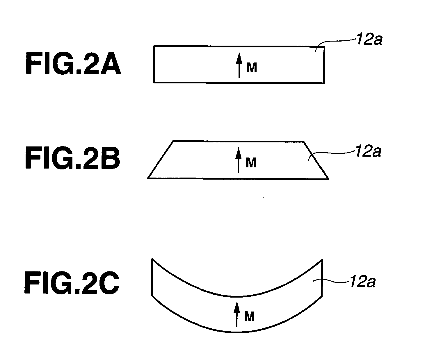
[0017]Making extensive investigations to attain the above object, the inventors have found that in an IPM or SPM rotary machine using a plurality of permanent magnet segments, better results are obtained when each of the permanent magnet segments is constructed as an assembly of further divided permanent magnet pieces (simply referred to as magnet pieces), and the coercive force or heat resistance near the surface of the magnet piece is higher than that in the interior of the magnet piece. In this connection, the inventors presumed that the method of Machida et al. and the method of WO 2006 / 043348 are suited for high-output rotary machines because of no loss of remanence, and since the coercive force near the surface of magnet pieces can be increased, the magnet pieces, when used in rotors in IPM or SPM rotary machines, are expected to minimize demagnetization due to heat generation by eddy currents. The inventors have found that application of such a method to individual magnet pieces of the permanent magnet assembly is effective in achieving the object of the invention, especially that a sintered Nd base magnet is used and divided into pieces for minimizing the heat generation by eddy currents, that the magnet pieces are used as the magnet for a rotor in a permanent magnet rotary machine, typically IPM or SPM rotary machine, and that magnet pieces in which the coercive force near their surface is higher than that in their interior, and in which heat resistance near their surface is improved are effective for use in a rotor in a permanent magnet rotary machine, typically IPM or SPM rotary machine.
[0028]The invention is successful in providing a permanent magnet rotary machine having a high output and heat resistance, the rotor of the machine being loaded with a permanent magnet, typically a sintered Nd base magnet, which has been divided into magnet pieces having a high remanence and a high coercive force, especially at an outer peripheral portion thereof, suited for use in rotors in IPM or SPM rotary machines.
Problems solved by technology
Permanent magnets are situated in rotary machines such that they are exposed to high temperature due to the heat generated by windings and cores and have a likelihood of demagnetization by the diamagnetic field from the windings.
While division of a magnet body into smaller pieces leads to a more reduction of eddy current loss, it becomes necessary to take into account such problems as an increase of manufacturing cost and a lowering of output due to a reduction of magnet volume by increased interstices.
That is, the amount of heat generated by eddy currents is greater near the magnet surface, so that the magnet surface region assumes a higher temperature and becomes prone to demagnetization.
Accordingly, the attempt to increase the coercive force by the above approach fails to avoid a lowering of remanence.
However, this measure cannot be practically acceptable because it compromises densification by sintering.
An alternative method of sintering at lower temperatures while applying stresses by means of a hot press or the like enables densification, but poses the problem of extremely reduced productivity.
However, there is still left the problem of poor productivity associated with the deposition of metal coating by sputtering or the like.
Method used
View moreImage
Smart ImageViewing Examples

Examples
example
[0058]Examples are given below for illustrating some embodiments of the present invention, but the scope of the invention is not limited thereby.
Login to View More PUM
 Abstract
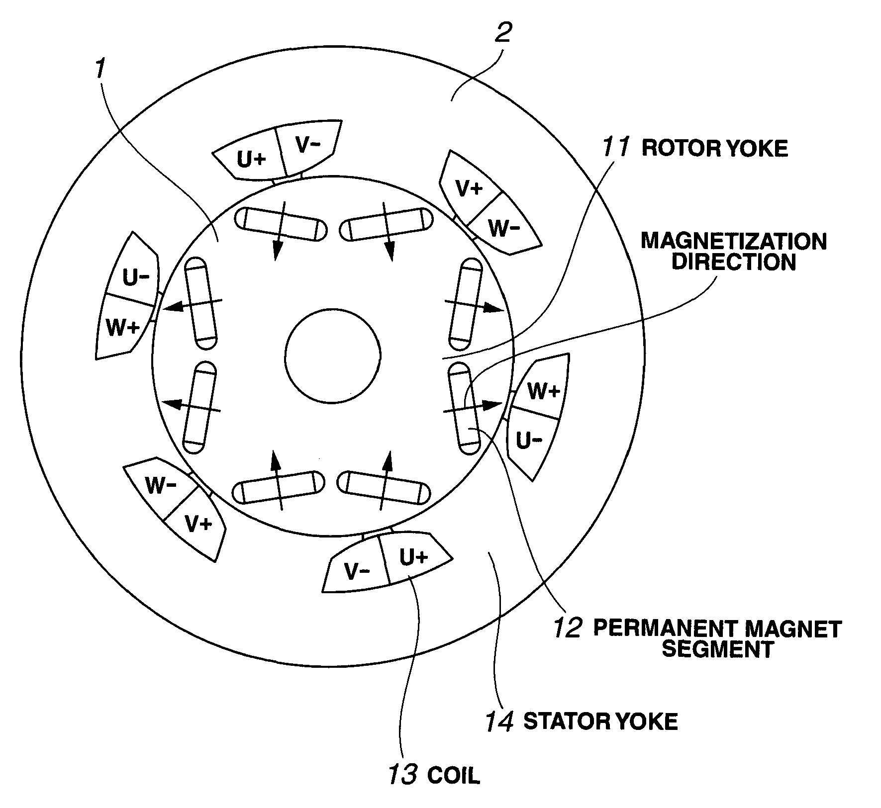
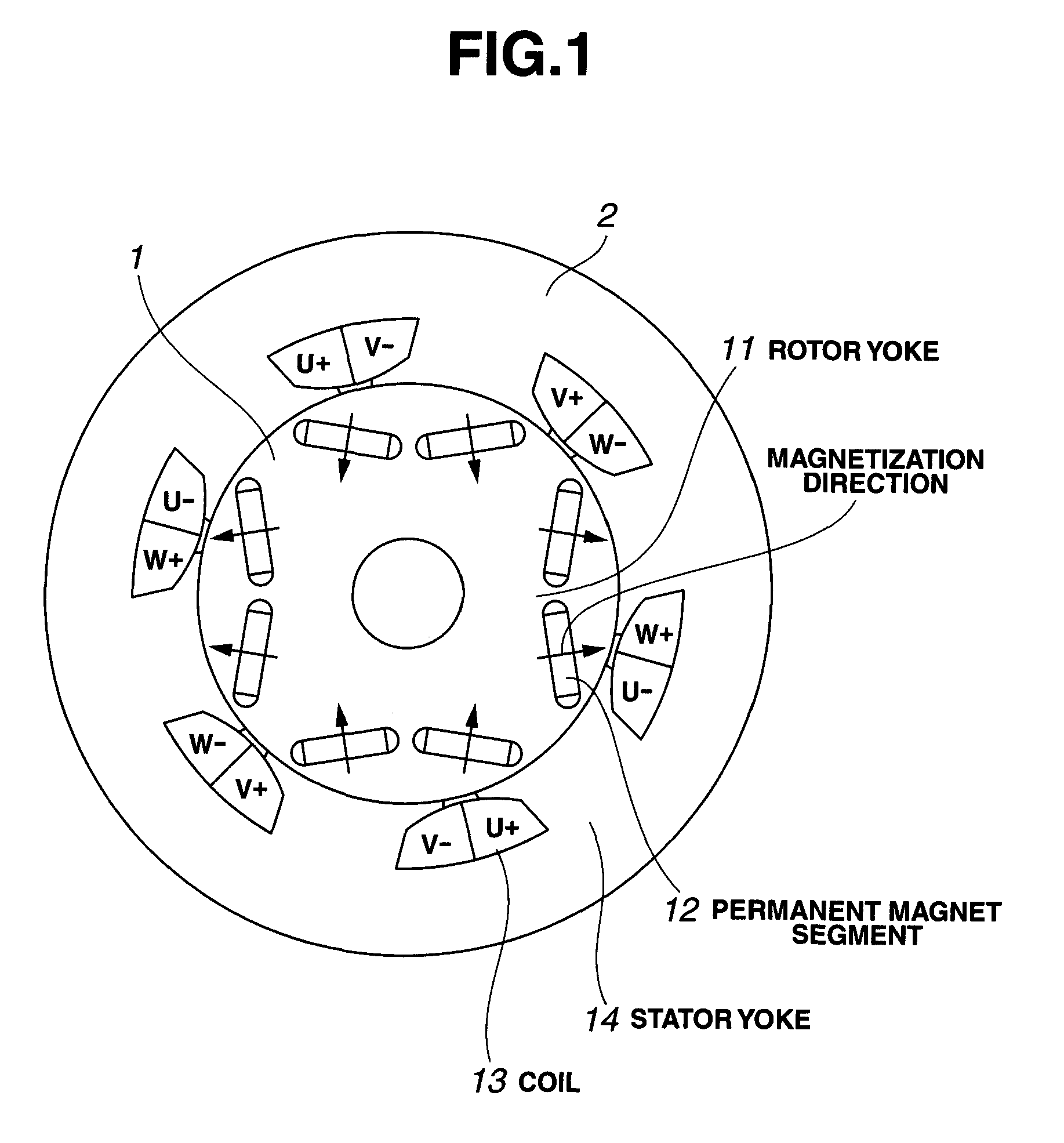
In connection with a permanent magnet rotary machine comprising a rotor comprising a rotor core and a plurality of permanent magnet segments embedded in the rotor core and a stator comprising a stator core having a plurality of slots and windings therein, the rotor and the stator being disposed to define a gap therebetween, or a permanent magnet rotary machine comprising a rotor comprising a rotor core and a plurality of permanent magnet segments mounted on the surface of the rotor core and a stator comprising a stator core having a plurality of slots and windings therein, the rotor and the stator being disposed to define a gap therebetween, the rotor wherein each of the permanent magnet segments is an assembly of further divided permanent magnet pieces, and the coercive force near the surface of the magnet piece is higher than that in the interior of the magnet piece.
Description
BACKGROUND OF INVENTION[0001]1. Technical Field[0002]This invention relates to a rotor for use in a permanent magnet rotary machine comprising a rotor comprising a rotor core and a plurality of permanent magnet segments embedded in the rotor core and a stator comprising a stator core having a plurality of slots and windings therein, the rotor and the stator being disposed to define a gap therebetween (generally referred to as interior permanent magnet (IPM) rotary machine), or a rotor for use in a permanent magnet rotary machine comprising a rotor comprising a rotor core and a plurality of permanent magnet segments mounted on the surface of the rotor core and a stator comprising a stator core having a plurality of slots and windings therein, the rotor and the stator being disposed to define a gap therebetween (generally referred to as surface permanent magnet (SPM) rotary machine), and more particularly, to a rotor for use in a permanent magnet structure rotary machine best suited a...
Claims
Login to View More Application Information
Patent Timeline
 Patent Type & AuthorityApplications(United States)
IPC IPC(8): H02K21/14
CPCH02K1/2766H02K21/14H02K21/12H02K1/278
InventorMIYATA, KOJIMIYATA, MINORIMINOWA, TAKEHISANAKAMURA, HAJIMEHIROTA, KOICHI
OwnerSHIN ETSU CHEM IND CO LTD