90-260Vac Dimmable MR16 LED Lamp

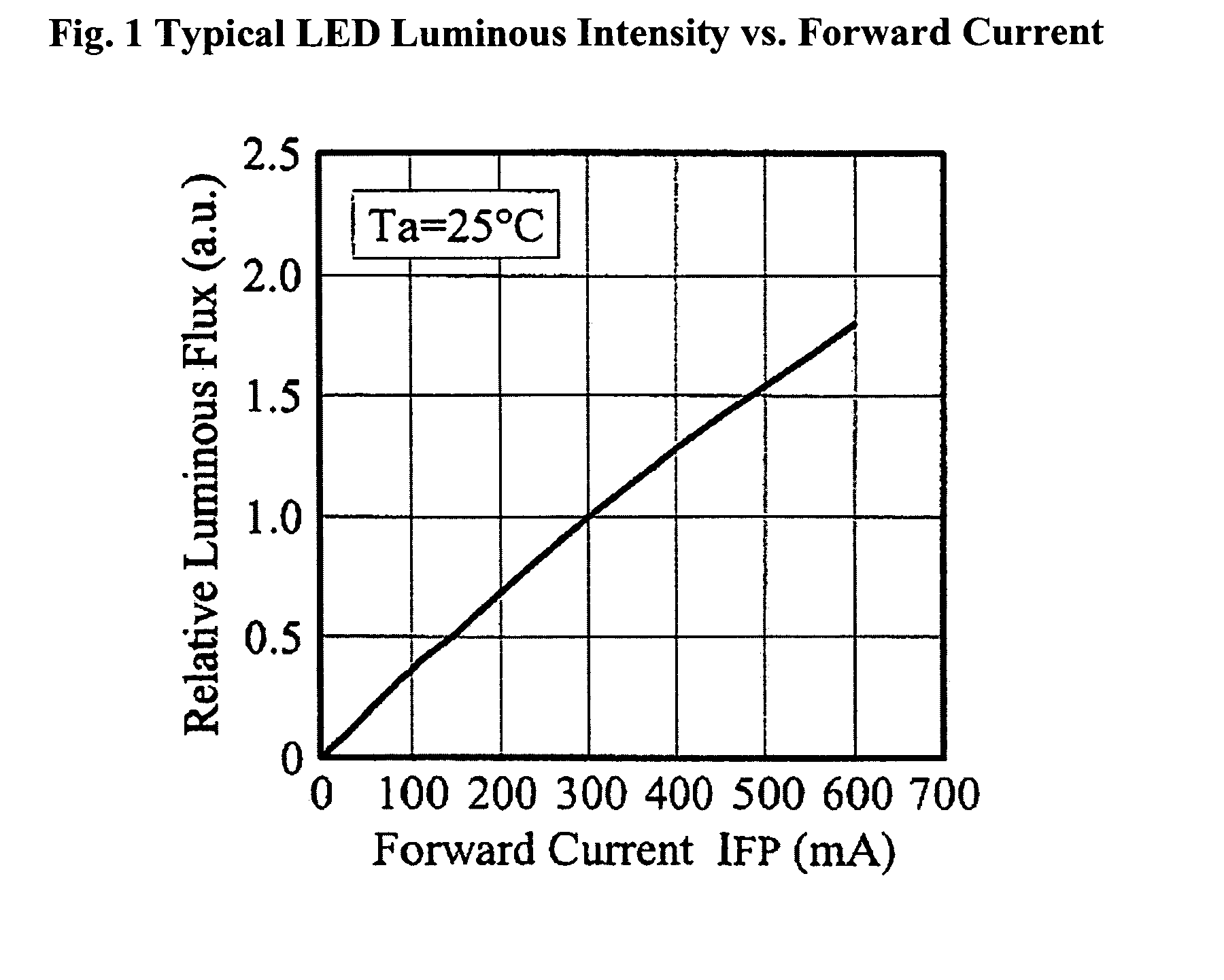
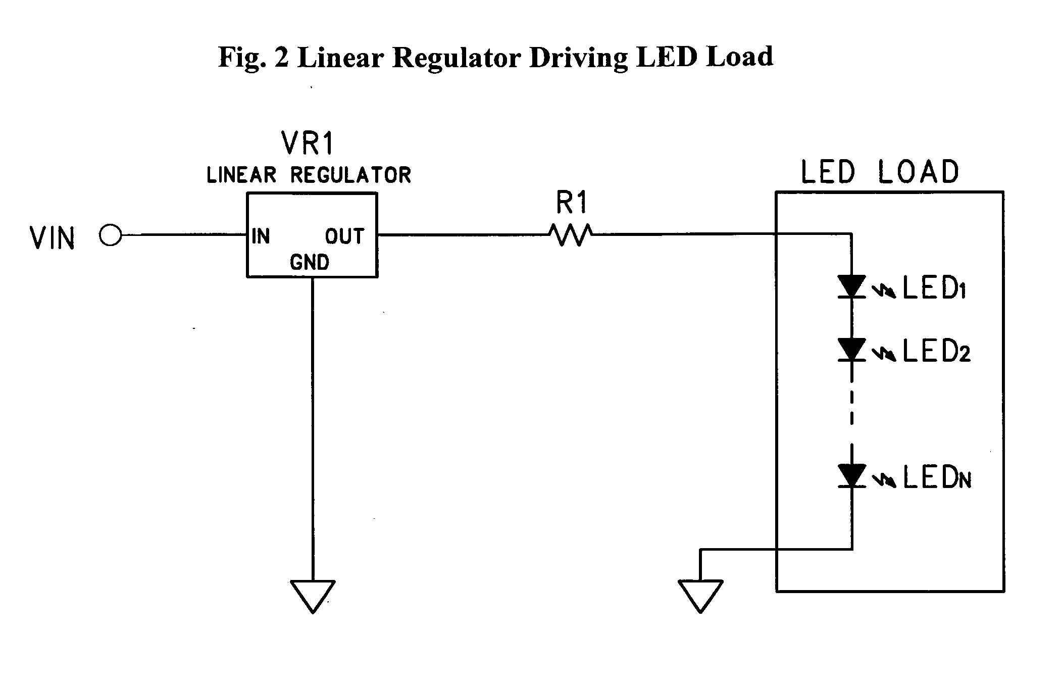
a dimmable, led lamp technology, applied in the direction of cathode-ray/electron beam tube circuit elements, lighting and heating apparatus, instruments, etc., can solve the problems of large changes, linear regulators are not very efficient circuits, and the level of forward current will degrade faster

Active Publication Date: 2011-03-24
BOCA FLASHER
View PDF6 Cites 47 Cited by
  • Summary
  • Abstract
  • Description
  • Claims
  • Application Information

AI Technical Summary

Problems solved by technology

LEDs driven at higher levels of forward current will degrade faster, and therefore have a shorter useful life, than the same LEDs driven at lower levels of forward current.
For this reason, linear regulators are not very efficient circuits when the input voltage is much larger than the required output voltage.
However, LEDs are not linear devices and small changes in voltage result in large changes in current which correspondingly effect large changes in output intensity.
The lower power efficiency of linear regulators makes them a poor choice in large power systems and in systems where the input voltage is much larger than the required LED driving voltage, such as when a 120 Vac or 240 Vac line voltage is used to drive a small number of LEDs.
As such, these systems can not practically employ them.
However, it requires control circuitry and user interface equipment which adds a level of cost and complexity to the lighting system.
However the dimming is very non-linear and these regulators are not practical for use in line-voltage applications driving a small LED Lamp.
This is an especially impractical method of dimming when there is a large difference between the nominal (undimmed) input voltage and the regulating threshold such as the line-voltage LED Lamp situation.
Another problem with dimming switching regulator drivers by lowering their input voltage

Method used


Image

  • 90-260Vac Dimmable MR16 LED Lamp
  • 90-260Vac Dimmable MR16 LED Lamp
  • 90-260Vac Dimmable MR16 LED Lamp

Examples


Embodiment Construction

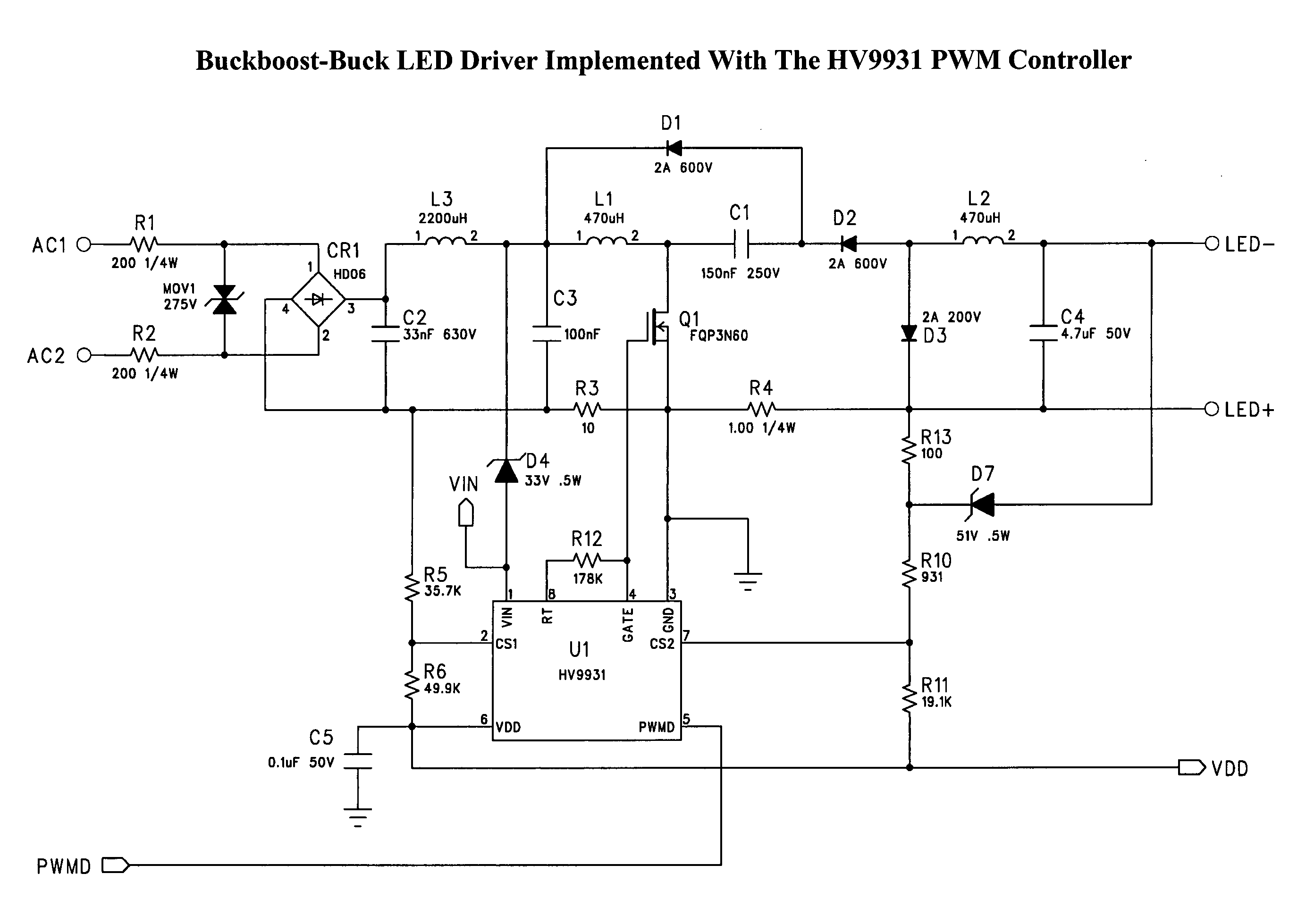
[0033]FIG. 5 is a simplified schematic diagram of Supertex Inc's proprietary single-stage, single-switch, non-isolated topology, cascading an input power factor correction (PFC) buck-boost stage and an output buck converter power stage. This transformerless power converter topology offers numerous advantages useful for driving high-brightness LEDs, including unity power factor, low harmonic distortion of the input AC line current, and low output current ripple. The output load is decoupled from the input voltage with a capacitor making the driver inherently failure-safe for the output load. This power converter topology also permits reducing the size of the filter capacitor needed, enabling use of non-electrolytic capacitors.

[0034]Referring to FIG. 5, the input buck-boost stage consisting of L1, C1, D1 and D4 is cascaded with an output buck stage including L2, D2, D3 and Co. Both converter stages share a single power MOSFET M1. The input buck-boost stage operates in discontinuous co...


PUM


Abstract

A line voltage LED Lamp produces variable illumination in response to industry standard lighting dimmers, through the use of an input voltage monitoring circuit which variably controls the current output of an integral driver in response to sensed changes in the input voltage. A cascaded converter circuit is used to achieve a very high step-down ratio, enabling the LEDs to be driven from a high input voltage without the need for a power transformer. Electrolytic capacitors are avoided, increasing the life of the driver circuit in the high ambient temperatures typically encountered in the base of similar lamps. The circuit employed drives high power LEDs, and the lamp is adapted to fit common MR16 size fixtures. Illumination output equivalent to similar size halogen bulbs is achieved.

Description

FIELD OF THE INVENTION[0001]This invention relates to illumination devices such as LEDs (light emitting diodes). The use of LEDs in illumination systems is well known. These devices are especially useful for lighting components, systems, and finished goods. LED lighting is a fast growing segment of the lighting industry due to the efficiency, reliability and longevity of LEDs. Product usage applications include but are not limited to interior and exterior signage, cove lighting, architectural lighting, display case lighting, under water lighting, marine lighting, informational lighting, task lighting, accent lighting, ambient lighting and many others. Special adaptations included in the present invention make the product especially suitable for retrofitting into existing lighting fixtures designed for high voltage MR16 size halogen bulbs.INCORPORATION BY REFERENCE AND OTHER REFERENCES[0002]Applicant incorporates by reference the following: U.S. patent application Ser. No. 12 / 385,613...

Claims


Application Information

Patent Timeline
IPC IPC(8): H05B37/02
CPCH05B33/0815H05B45/38H05B45/355H05B45/375H05B45/3725
Inventor MCKINNEY, STEVEN
Owner BOCA FLASHER
Why Eureka
Try Eureka