
Card Connector with Ejection Damper

Active Publication Date: 2011-03-24
MOLEX INC
View PDF7 Cites 5 Cited by
  • Summary
  • Abstract
  • Description
  • Claims
  • Application Information

AI Technical Summary

Benefits of technology

[0010]The present invention aims at overcoming the above-mentioned problems encountered by the conventional card connector, and makes it an object to provide a card connector configured in a manner such that a viscous dampening material such as a grease or other lubricant is applied between a slide surface of a guide member of a card guide mechanism, and a guide surface that guides the guide member. This material has the capability of exhibiting a damping effect provided by the lubricant when a slide member is returned by an urging member. Further, the stable damping effect can be attained by an additional arrangement such that an abutment part slidingly contacts with the inner side of a case thereby to limit its upward movement in order to maintain a spacing between the guide surface and the slide surface within a predetermined amount. This arrangement eliminates the necessity to separately dispose a mechanism for speed reduction, thus permitting a simple, low cost, and miniature structure. This arrangement also slows down the speed of the guide member during discharging of a card, so that a card is not permitted to be rapidly ejected toward the exterior, and reduces mechanical shock when the guide member is stopped.

Problems solved by technology

This arrangement also slows down the speed of the guide member during discharging of a card, so that a card is not permitted to be rapidly ejected toward the exterior, and reduces mechanical shock when the guide member is stopped.

Method used


Image

  • Card Connector with Ejection Damper
  • Card Connector with Ejection Damper
  • Card Connector with Ejection Damper

Examples


Embodiment Construction

[0037]Preferred embodiments of the present invention will now be described in detail with reference to the accompanying drawings.

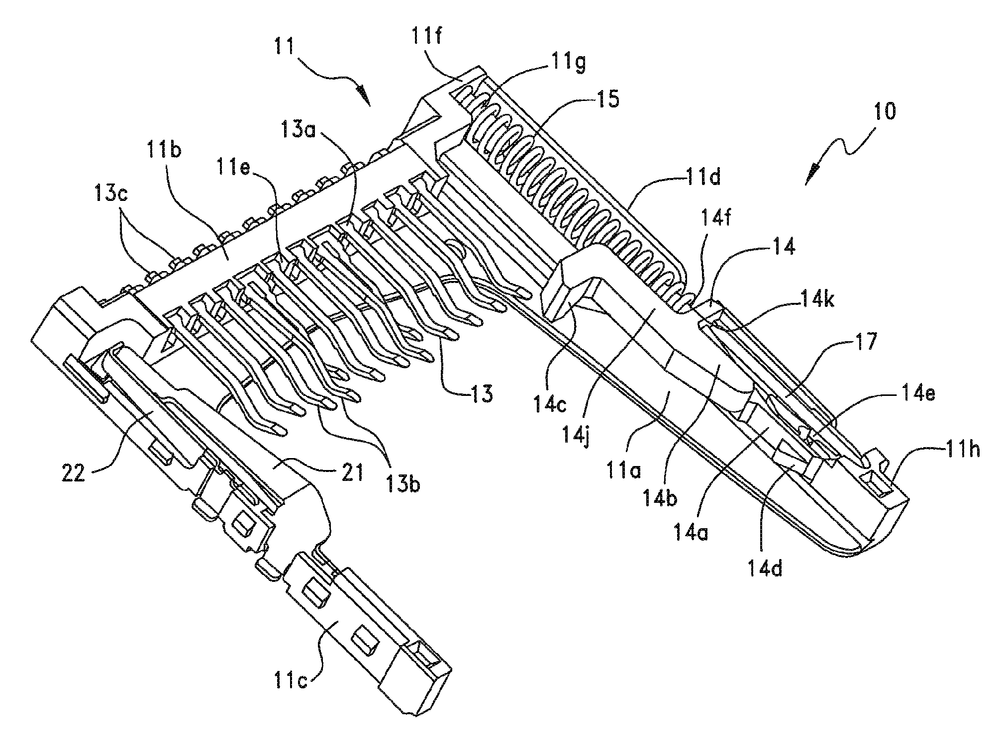
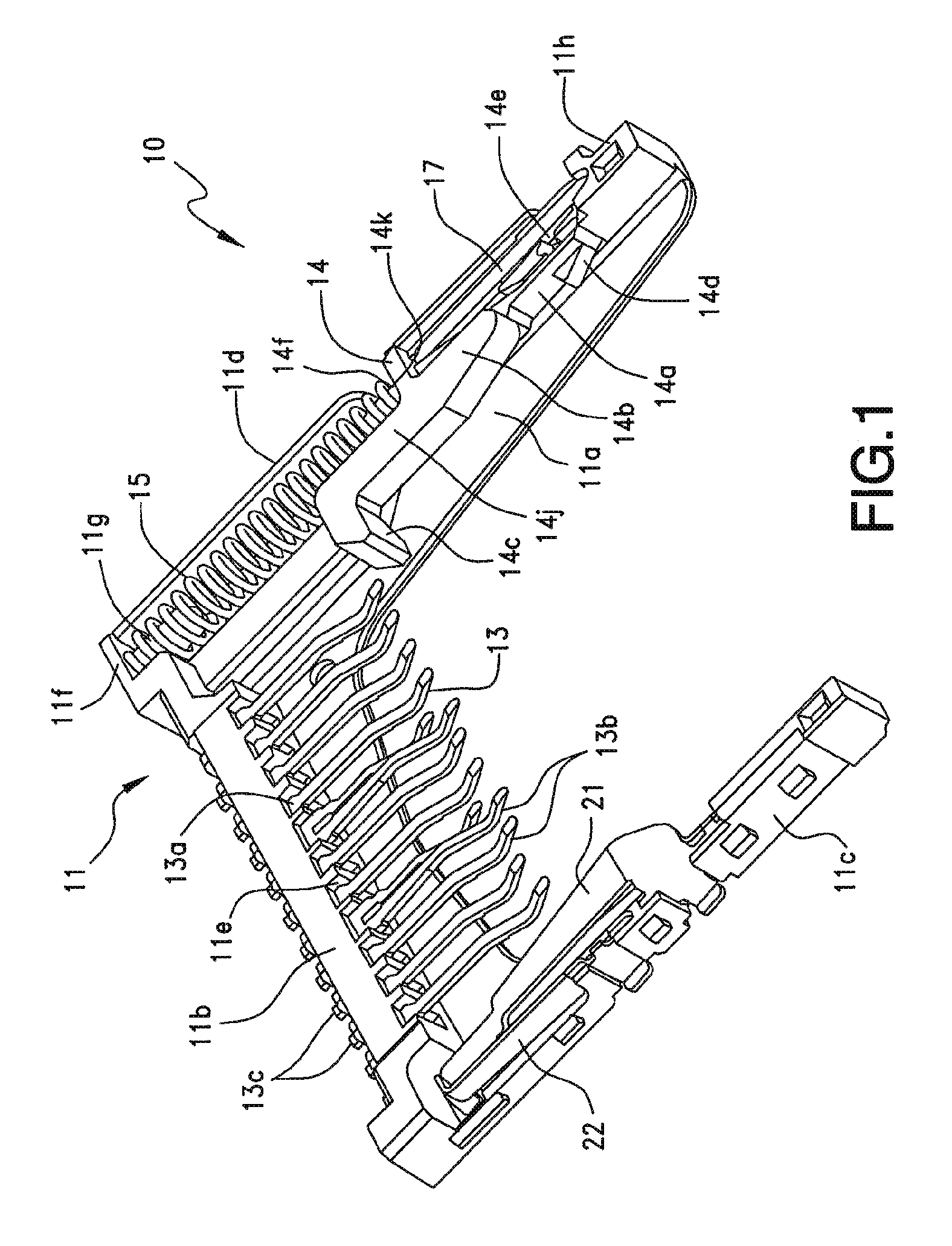
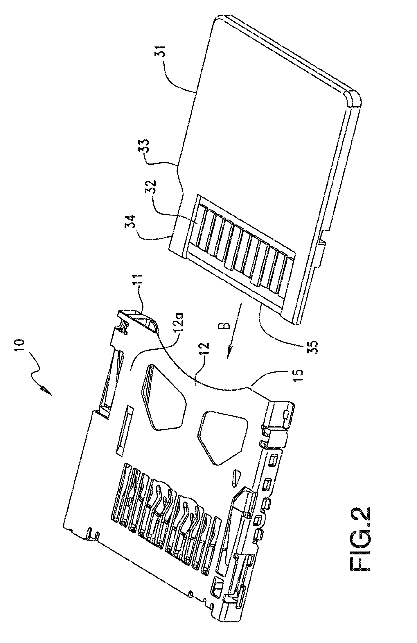
[0038]Referring first to FIGS. 1 and 2, a card connector, generally indicated at 10, according to a first preferred embodiment is shown. Card connector 10 is configured to be attached to electronic equipment (not shown) and receive a card 31 therein, so that card 31 is attached via the card connector 10 to the electronic equipment. For example, the electronic equipment may be any type of equipment such as a personal computer, a portable or mobile telephone, a PDA, a digital camera, a video camera, a music player, a game machine, a car navigation system, or the like.

[0039]The card 31 may be any kind of card, for example, an IC card such as an SIM card, MMC®, an SD ® card, a mini SD® card, an xD picture card®, a memory stick®, a memory stick Duo®, a smart media®, a T-Flash memory card, a micro SD®, or the like. The first preferred embodiment describes the ca...


PUM


Abstract

A card connector has a housing with a base and a side rail extending from the base to define a card-insertion cavity. A plurality of conductive terminals are supported by the housing and extend at least partially into the card-insertion cavity for contacting a card inserted into the card-insertion cavity. A push-push style card locking and ejection mechanism retains the card in the card-insertion cavity upon a first push and which ejects an inserted card upon a second push. The mechanism includes a slide member positioned for slidable movement on the side rail and a biasing member contacting the slide member for selectively exerting an ejection force on the slide member. The slide member includes a slide surface that slides along a guide surface of the side rail. A damping material is interposed between the slide member slide surface and the guide rail guide surface for retarding movement of the slide member on the side rail in response to an ejection force from the biasing member.

Description

BACKGROUND OF THE INVENTION[0001]1. Field of the Invention[0002]The present invention relates to a card connector and more particularly to a card connector with an ejection damper.[0003]2. Description of the Related Art[0004]Conventionally, electronic equipment, such as a personal computers, portable or mobile telephones, PDAs (personal digital assistant), digital cameras, video cameras, music players, game machines, and car navigation systems, are equipped with card connectors adapted for use with various types of memory cards such as a SIM (subscriber identity module) card, an MMC® (multi media card), an SD® (secure digital) card, a mini SD® card, an xD picture card® (xD-Picture card), a memory stick®, a memory stick Duo®, a smart media®, a T-Flash (Trans-Flash) memory card, a micro SD® card, and the like.[0005]Recent card connectors generally have, for ease of handling, a “push-push” structure in which a user handles a memory card so as to push it in order to both insert and disc...

Claims


Application Information

Patent Timeline
IPC IPC(8): H01R13/62
CPCA45C2011/188G06K13/0843G06K13/0806G06K7/0047H01R31/06
Inventor MATSUMOTO, YASUYOSHITOMITA, MITSUHIROTAKEUCHI, YOKO
Owner MOLEX INC
Learn More