System and method using low emissions gas turbine cycle with partial air separation

a gas turbine and partial air separation technology, applied in the field of gas turbine power plants, can solve the problems of large footprint, increased ammonia slip, and high cost of selective catalytic reactors, and achieve the effect of reducing the risk of nox emissions

Inactive Publication Date: 2011-03-31
GENERAL ELECTRIC CO
View PDF13 Cites 77 Cited by
  • Summary
  • Abstract
  • Description
  • Claims
  • Application Information

AI Technical Summary

Benefits of technology

[0011]enriching the products of combustion from the first stage with oxygen in a second stage; and

Problems solved by technology

One of the solutions currently in use to reduce these NOx emissions employs selective catalytic reactors (SCR)s. Selective catalytic reactors undesirably are expensive, have a large footprint, and present additional concerns regarding ammonia slip.

Method used


Image

  • System and method using low emissions gas turbine cycle with partial air separation
  • System and method using low emissions gas turbine cycle with partial air separation
  • System and method using low emissions gas turbine cycle with partial air separation

Examples


Embodiment Construction

[0019]While the methods and apparatus are herein described in the context of a gas turbine engine used in an industrial environment, it is contemplated that the method and apparatus described herein may find utility in other combustion turbine systems applications including, without limitation, turbines installed in aircraft. Further, the principles and teachings set forth herein are applicable to gas turbine engines using a variety of combustible fuels such as, but not limited to, natural gas, gasoline, kerosene, diesel fuel, and jet fuel.

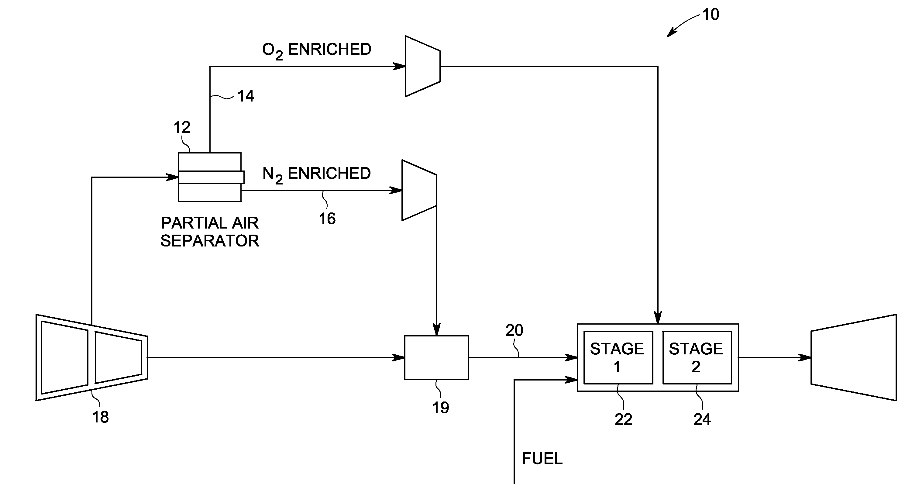
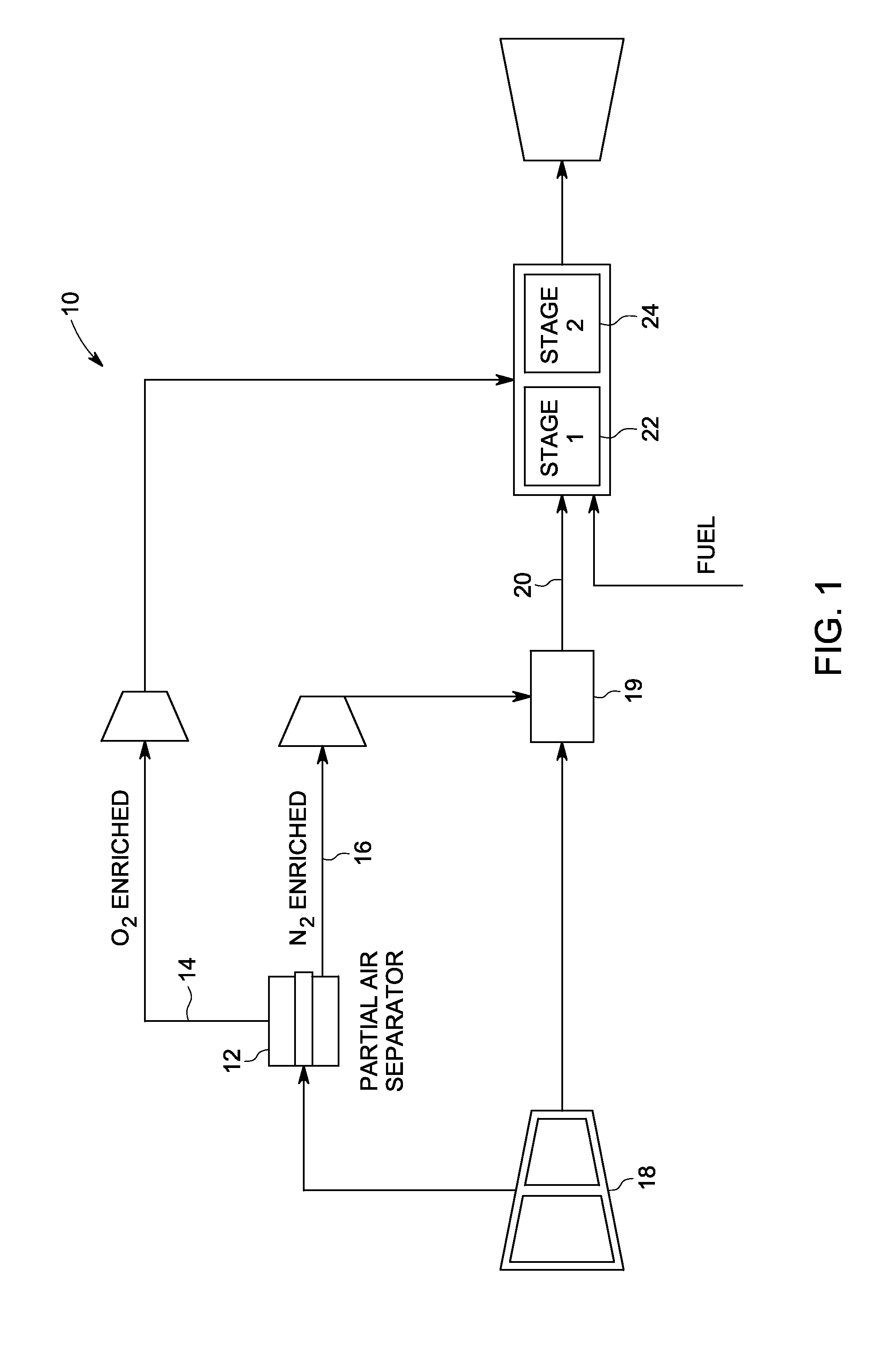
[0020]FIG. 1 is a simplified block diagram illustrating a low emissions simple gas turbine system 10 with partial air separation, according to one embodiment. Gas turbine system 10 employs a partial air separator 12 that operates to separate compressed air supplied via an air compressor 18 into an oxygen enriched gas stream 14 and a nitrogen enriched gas stream 16. Input air is compressed via the air compressor 18; and the compressed air is suppli...


PUM


Abstract

A system and method of reducing gas turbine nitric oxide emissions includes a first combustion stage configured to burn air vitiated with diluents to generate first combustion stage products. A second combustion stage is configured to burn the first combustion stage products in combination with enriched oxygen to generate second combustion stage products having a lower level of nitric oxide emissions than that achievable through combustion with vitiated air alone or through combustion staging alone.

Description

BACKGROUND[0001]This invention relates generally to gas turbine power plants, and more particularly, to a system and method for reducing gas turbine nitric oxide (NOx) emissions without incurring penalties associated with either combustion efficiency or carbon monoxide (CO) emissions.[0002]Pollutant emissions from gas turbine power plants have been of great concern in the past several decades. Stringent regulations have been established to lower these emissions, especially nitric oxides to single digits. One of the solutions currently in use to reduce these NOx emissions employs selective catalytic reactors (SCR)s. Selective catalytic reactors undesirably are expensive, have a large footprint, and present additional concerns regarding ammonia slip.[0003]Combustion with vitiated air is a proven technique for reducing NOx emissions by affecting the NOx kinetic mechanisms, changing the flame structure and lowering the peak flame temperature. Combustion staging has also been shown to re...

Claims


Application Information

Patent Timeline
Patent Type & Authority Applications(United States)
IPC IPC(8): F02C9/26
CPCF02C3/22F23C2900/99011F23L7/00F23L2900/07002F23L2900/07005F02C3/20F23R2900/00002Y02E20/16Y02E20/344Y02T50/678F23R3/346Y02E20/34
Inventor ELKADY, AHMED MOSTAFAJOSHI, NARENDRA DIGAMBERKULKARNI, PARAG PRAKASHVANDERVORT, CHRISTIAN LEEVENKATESAN, KRISHNAKUMAR
Owner GENERAL ELECTRIC CO
Why Eureka
Try Eureka