Oxyfuel Combustion Boiler Plant and Operation Method of Oxyfuel Combustion Boiler Plant

a technology of oxyfuel combustion boiler and boiler plant, which is applied in the direction of combustion types, emission prevention, lighting and heating apparatus, etc., can solve the problems of abnormal combustion, backfire, and pulverized coal entering a mass

Active Publication Date: 2011-03-31
MITSUBISHI POWER LTD
View PDF6 Cites 13 Cited by
  • Summary
  • Abstract
  • Description
  • Claims
  • Application Information

AI Technical Summary

Benefits of technology

[0012]According to the present invention, an oxyfuel combustion boiler plant or an operation method of the...

Problems solved by technology

However, when injecting oxygen toward the mixture flow of pulverized coal and combustion exhaust gas, there is the possibility that pulverized coal may enter a mass of gas having a high oxygen ...

Method used


Image

  • Oxyfuel Combustion Boiler Plant and Operation Method of Oxyfuel Combustion Boiler Plant
  • Oxyfuel Combustion Boiler Plant and Operation Method of Oxyfuel Combustion Boiler Plant
  • Oxyfuel Combustion Boiler Plant and Operation Method of Oxyfuel Combustion Boiler Plant

Examples


embodiment 1

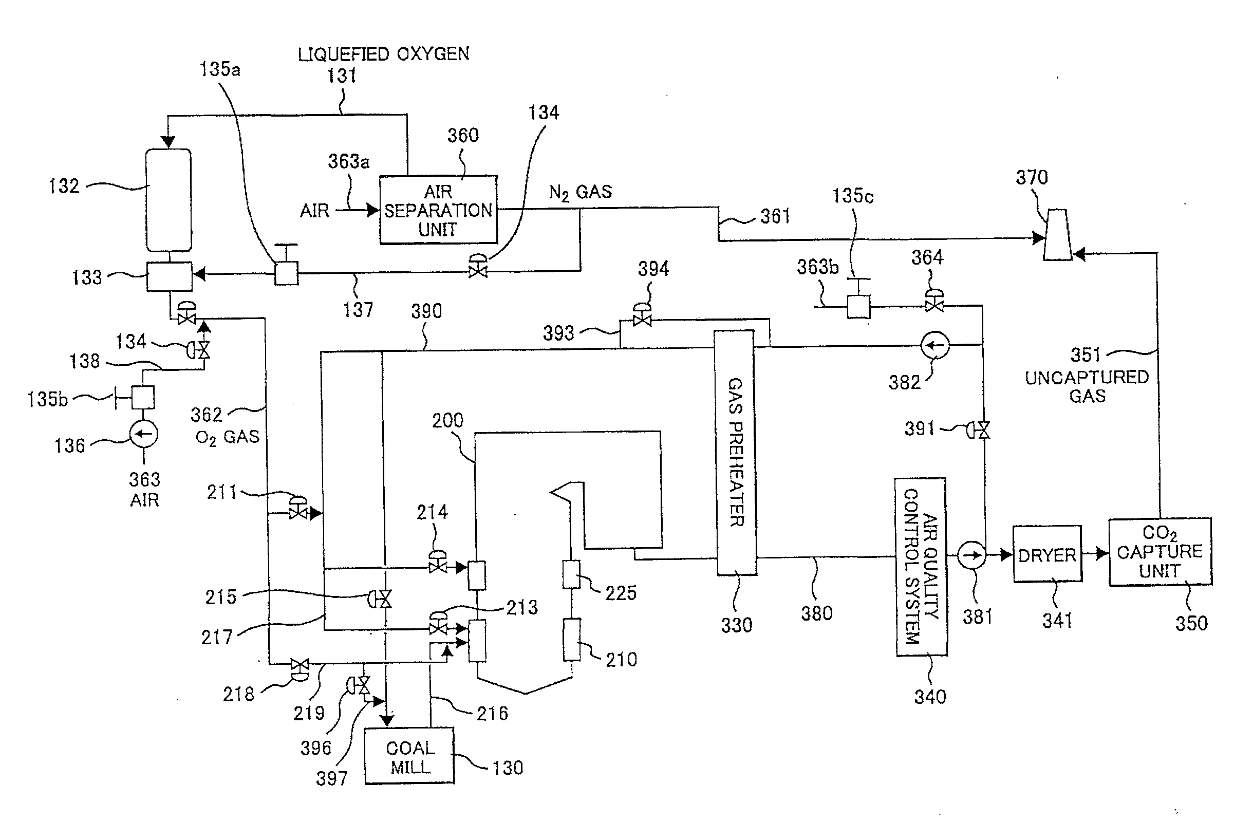
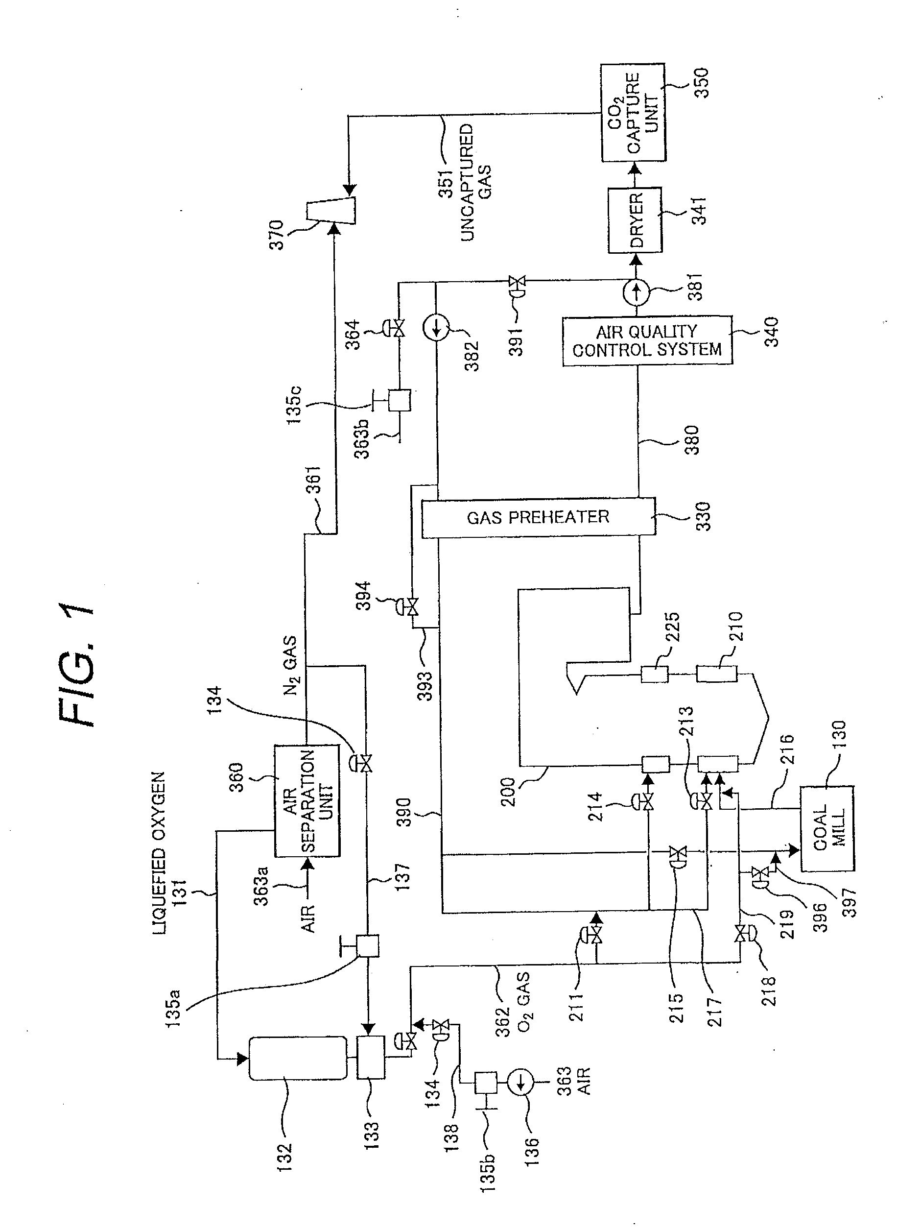
[0031]FIG. 1 shows an oxyfuel combustion boiler plant using coal as fuel. This embodiment is a thermal power plant for generating steam using a boiler 200.

[0032]The boiler 200 includes a burner 210 and a gas port 225. The burner 210 supplies and burns pulverized coal to the furnace in the boiler. The gas port 225 is installed on the downstream side of the burner 210 and supplies second stage combustion gas to the furnace.

[0033]The system pipes through which combustion exhaust gas discharged from the boiler 200 flows will be explained below. Combustion exhaust gas 380 indicates the system pipe through which the exhaust gas discharged from the boiler 200 flows. An air quality control unit 340 is an apparatus for purifying exhaust gas. A fan 381 is a unit for letting exhaust gas flow. A dryer 341 cools exhaust gas and simultaneously removes hygroscopic moisture. A CO2 capture unit 350 compresses exhaust gas after drying and captures carbon dioxide from the exhaust gas. Uncaptured gas 3...

embodiment 2

[0075]FIG. 10 shows a modification of the supply method of the oxygen gas 362. The difference from FIG. 1 is that the oxygen gas 362 is supplied to the primary system pipe 216 in two stages instead of one. By doing this, the occurrence of abnormal combustion can be suppressed furthermore.

[0076]An example of the mixing state of gas and pulverized coal when the oxygen gas 362 is supplied to a flow 31 of the primary system gas is shown in FIG. 11. FIG. 11 shows the mixing state when the oxygen gas 362 is supplied at one time.

[0077]The oxygen gas 362 is injected from the oxygen supply nozzle 52 toward the flow 31 of the primary system gas. On the boundary between the oxygen gas 362 and the flow 31 of the primary system gas, a mixing region 32 is formed. However, the injected gas is not all mixed instantaneously. Therefore, inside the mixing region 32, a mass of gas of a high oxygen concentration 33 is formed temporarily. The flow 31 of the primary system gas is accompanied with pulveriz...

embodiment 3

[0081]FIG. 13 shows the burner structure and an example of the supply method of the oxygen gas 362. The primary gas 10 is injected from the central part of the burner into the boiler furnace. A flame stabilizer 89 accelerates the ignition of pulverized coal. Secondary system gas 217 is supplied from the circumference of the primary system gas 10. The burner divides the secondary system gas 217 into two flow paths.

[0082]The oxygen supply nozzle 52 is installed inside the primary system pipe 216 on the upstream side of the burner. The oxygen supply nozzle 52 is divided into two parts in the flow direction of the primary system gas 10. This method has an advantage in that the primary system gas in the boiler furnace or in the primary system gas immediately after oxygen gas is injected, oxygen concentration irregularities are hardly produced. If the oxygen concentration irregularities are small, there is an advantage that the combustion properties such as the NOx discharge characteristi...


PUM


Abstract

An oxyfuel combustion boiler plant comprising:
    • a boiler having an air separation unit for manufacturing oxygen by separating nitrogen from air, a burner for burning the oxygen supplied from the air separation unit and pulverized coal, and a primary system pipe for supplying the pulverized coal to the burner, exhaust gas recirculation system pipe for supplying combustion exhaust gas discharged from the boiler to the primary system pipe, a carbon dioxide capture unit for capturing carbon dioxide in the exhaust gas discharged from the boiler, the oxyfuel combustion boiler plant is further comprising: an oxygen buffer tank disposed on a downstream side of the air separation unit; an oxygen supply pipe for supplying oxygen to the primary system pipe of the burner from the oxygen buffer tank; and a nitrogen supply pipe for supplying a part of nitrogen generated from the air separation unit or an air supply pipe for supplying air from outside which is connected to the oxygen supply pipe on a downstream side of the oxygen buffer tank and on an upstream side of a junction of the primary system pipe.

Description

CLAIM OF PRIORITY [0001]The present application claims priority from Japanese patent application serial No. 2009-225912, filed on Sep. 30, 2009, the content of which is hereby incorporated by reference into this application.BACKGROUND OF THE INVENTION [0002]1. Field of the Invention[0003]The present invention relates to an oxyfuel combustion boiler plant and an operation method of the oxyfuel combustion boiler plant.[0004]2. Description of Related Art[0005]A boiler for burning pulverized coal can be divided into two kinds of combustion systems depending on the gas to be supplied to a burner. Air-fuel combustion is of a system for burning fuel by supplying air to the burner. Further, oxyfuel combustion is of a system for burning fuel by a mixture of high purity oxygen and combustion exhaust gas instead of air.[0006]In the oxyfuel combustion, the exhaust gas components are mostly carbon dioxide, so when capturing carbon dioxide from exhaust gas, there is no need to concentrate the car...

Claims


Application Information

Patent Timeline
IPC IPC(8): F23C10/00
CPCF23C9/003F25J2260/80F23C2900/06041F23J2215/50F23L7/007F23L2900/07001F23L2900/07005F23L2900/07006Y02E20/322Y02E20/344F25J3/04533F25J2215/02F25J2245/40F25J2245/42F23C2202/10Y02E20/32Y02E20/34
Inventor TANIGUCHI, MASAYUKISHIBATA, TSUYOSHIHAYASHI, YOSHIHARU
Owner MITSUBISHI POWER LTD
Why Eureka
Try Eureka