Charged particle irradiation system and method for controlling the same

a charge particle and irradiation system technology, applied in the direction of radiation therapy, chemical to radiation conversion, radiation therapy, etc., can solve the problem that the distribution of beam doses with which the spot group is irradiated may not be as desired, and achieve the effect of suppressing an operation, reducing treatment time, and suppressing an operation

Active Publication Date: 2011-03-31
HITACHI LTD
View PDF9 Cites 149 Cited by
  • Summary
  • Abstract
  • Description
  • Claims
  • Application Information

AI Technical Summary

Benefits of technology

[0021]According to the present invention, even when a relatively minor failure occurs during irradiation of a certain spot or the respiratory gating signal is turned off, the irradiation is continuously performed on a group that includes the certain spot. Thus, it is unnecessary that the irradiation be performed on the spot group multiple times separately (or it is unnecessary that the irradiation be interrupted ...

Problems solved by technology

Since, in such a case, unexpected gaps between spots or unexpected overlapped spots are generated, a...

Method used


Image

  • Charged particle irradiation system and method for controlling the same
  • Charged particle irradiation system and method for controlling the same
  • Charged particle irradiation system and method for controlling the same

Examples


Embodiment Construction

[0036]A charged particle irradiation system according to an embodiment of the present invention is described below in detail with reference to the accompanying drawings.

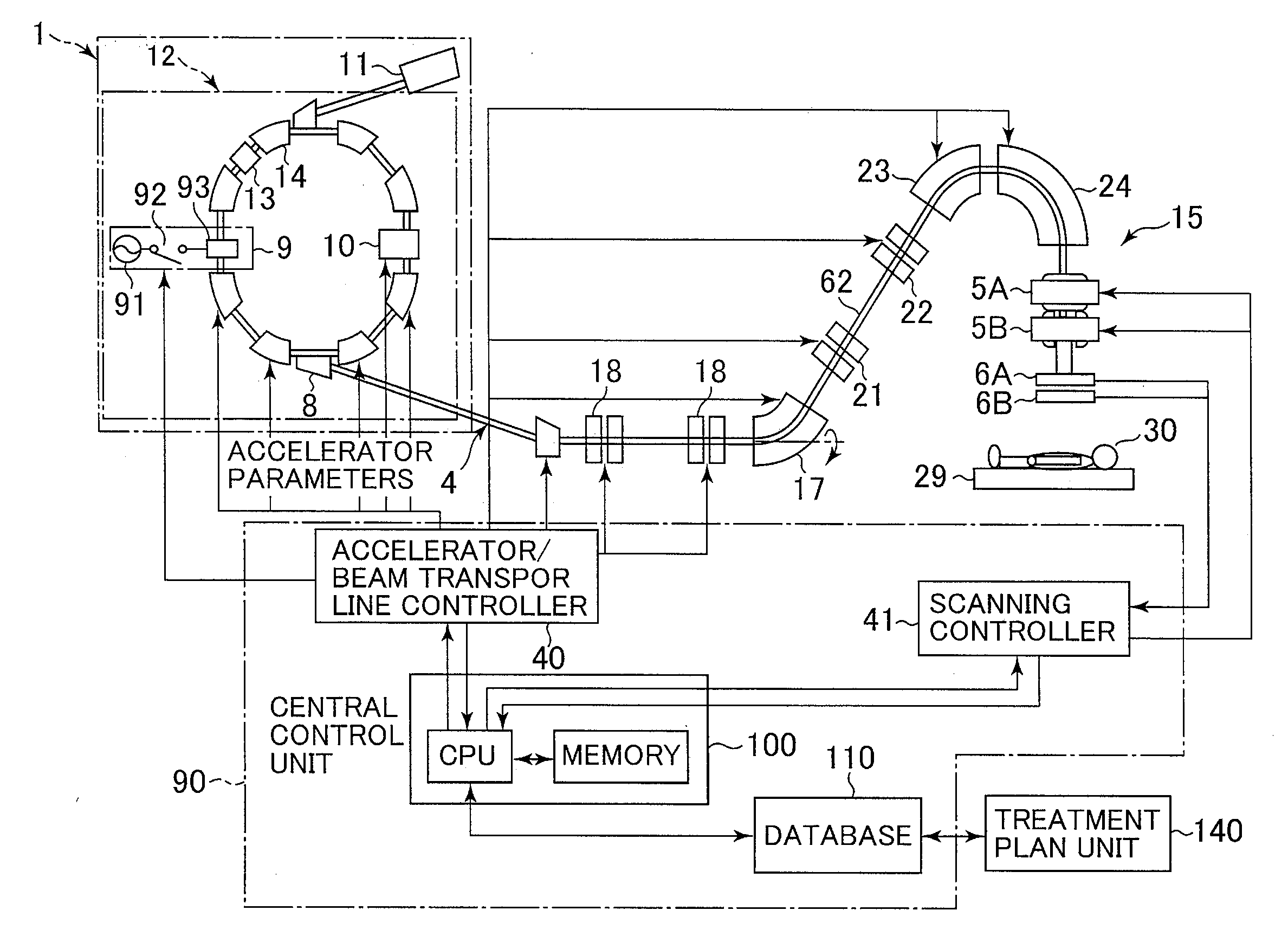
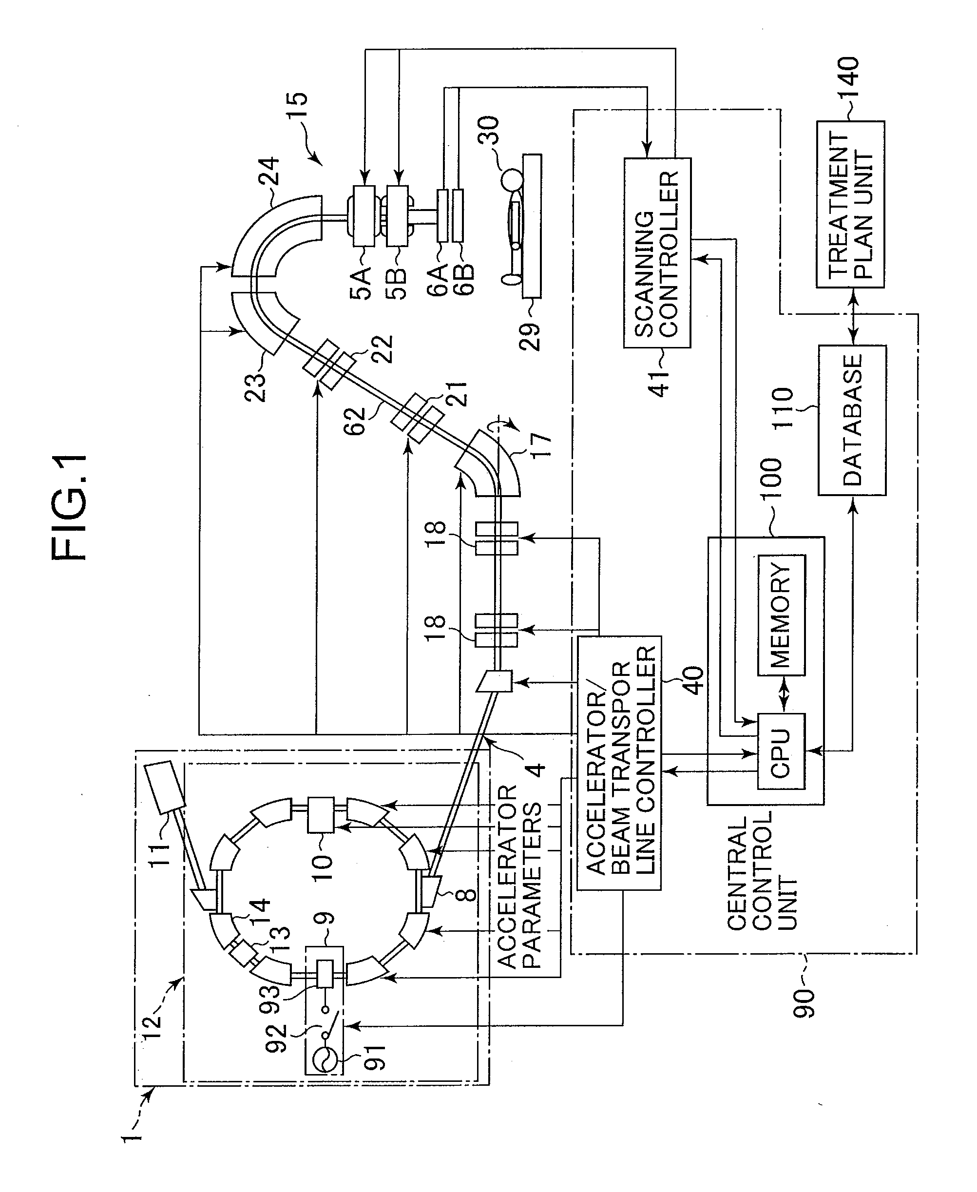
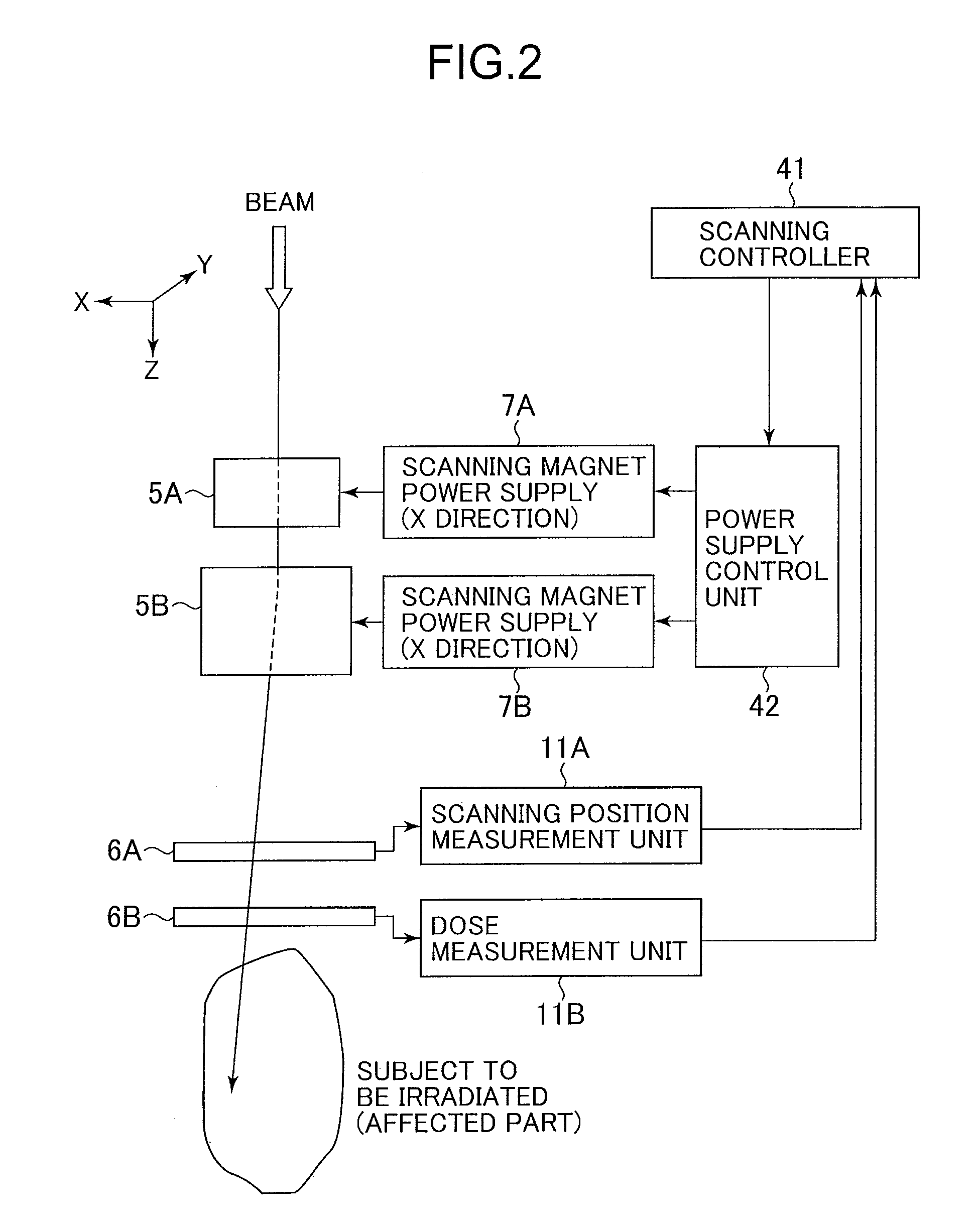
[0037]FIG. 1 is a conceptional diagram showing a proton beam irradiation system that serves as the charged particle irradiation system according to the embodiment of the present invention. FIG. 2 is a conceptional diagram showing a scanning irradiation unit that constitutes a part of the charged particle irradiation system according to the embodiment of the present invention.

[0038]Referring to FIG. 1, the charged particle irradiation system irradiates, with a charged particle beam (e.g., proton beam), an affected part of a patient who is fixed to a treatment bed placed in a treatment room. The charged particle irradiation system treats the affected part. The charged particle irradiation system includes an ion beam generator 1, a beam transport line 4, a scanning irradiation unit 15, and a control system 90. The beam ...


PUM


Abstract

A beam extraction process (interruption and restart) is appropriately performed when a failure occurs during irradiation of a spot group. A charged particle irradiation system includes a synchrotron 12 and a scanning irradiation unit 15 that scans an ion beam extracted from the synchrotron over a subject. The extraction of the ion beam from the synchrotron is stopped on the basis of a beam extraction stop command. Scanning magnets 5A and 5B are controlled to change a point (spot) to be irradiated with the ion beam, while the extraction of the ion beam is stopped. The extraction of the ion beam from the synchrotron is restarted after the change of the spot to be irradiated. When a relatively minor failure in which continuous irradiation would be possible occurs during irradiation of a certain spot with the beam, the extraction of the beam is not immediately stopped.

Description

BACKGROUND OF THE INVENTION[0001]1. Field of the Invention[0002]The present invention relates to a charged particle irradiation system and a method for controlling the charged particle irradiation system. The invention more particularly relates to a charged particle irradiation system that irradiates a patient with a charged particle beam such as protons or carbon ions and treats the patient, and a method for controlling the charged particle irradiation system.[0003]2. Description of the Related Art[0004]A treatment method is known for irradiating an affected part (cancer or the like) of a patient with a charged particle beam (ion beam) such as protons or carbon ions. A charged particle irradiation system used for such a treatment includes an ion beam generator, a beam transport line and an irradiation unit.[0005]Examples of irradiation methods adopted by the irradiation unit include a passive irradiation method in which a beam is spread by means of a scatterer and is then extracted...

Claims


Application Information

Patent Timeline
IPC IPC(8): G21G5/00
CPCA61N5/1037A61N5/1043A61N2005/1087A61N5/1064A61N5/1048
Inventor NATORI, TAKAYOSHIMORIYAMA, KUNIOMATSUDA, KOJI
Owner HITACHI LTD
Why Eureka
Try Eureka