Method of improving print performance in flexographic printing plates

a technology print performance, which is applied in the field of improving the print performance of flexographic printing plate, can solve the problems of affecting the printing effect, affecting the quality of the relief image, and affecting the effect of the printing effect, so as to achieve good results

Active Publication Date: 2011-04-07
MACDERMID PRINTING SOLUTIONS
View PDF38 Cites 152 Cited by
  • Summary
  • Abstract
  • Description
  • Claims
  • Application Information

AI Technical Summary

Benefits of technology

[0024]It is an object of the present invention to provide a relief image printing plate that produces a good result when printing on corrugated board substrates.
[0025]It is another object of the present invention to produce a relief image printing plate that reduces print fluting when printing on corrugated board substrates.
[0028]It is still another object of the present invention to control the surface roughness of the print surface of the relief image printing element.

Problems solved by technology

The exterior liner layer often has slight indentations due to the uneven support of the underlying flute layer.
A problem that may be encountered when printing on corrugated board substrates is the occurrence of a printing effect referred to as “fluting” (and which is also known as “banding” or “striping” or “washboarding”).
Fluting may occur, when printing the liner on the exterior surface of the corrugated board, after the corrugated board has been assembled.
Furthermore, increasing the printing pressure does not eliminate striping, and the increased pressure can cause damage to the corrugated board substrate.
It is very difficult to print small graphic elements such as fine dots, lines and even text using flexographic printing plates while maintaining open reverse text and shadows.
Maintaining small dots on flexographic plates can be very difficult due to the nature of the platemaking process.
The smallest of these dots are prone to being removed during processing, which means no ink is transferred to these areas during printing (the dot is not “held” on plate and / or on press).
Alternatively, if the dot survives processing they are susceptible to damage on press.
For example small dots often fold over and / or partially break off during printing causing either excess ink or no ink to be transferred.
A noted drawback to this method is that it is inconvenient and cumbersome and requires a large space for the apparatus.
However, the pre-sensitization step can also cause shadow tones to fill in, thereby reducing the tonal range of the halftones in the image.
In addition, if the photosensitive resin layer has a thickness of more than 0.1 mm, the weak light of the low intensity bump exposure dose does not sufficiently reach certain portions of the photosensitive resin layer (i.e., the side of the photosensitive layer that is closest to the substrate layer and furthest from the source of actinic radiation), at which the removal of the dissolved oxygen is insufficient.
In the subsequent main exposure, these portions will not cure sufficiently due to the remaining oxygen.
Unfortunately, these dyes are weak initiators and require protracted bump exposure times. In addition, these dyes sensitize the resin to regular room light, so inconvenient yellow safety light is required in the work environment.
Lastly, the approach described by Kawaguchi employs conventional broadband-type sources of actinic radiation light for bump exposure, and thereby also tends to leave significant amounts of oxygen in the lower layers of the resin.
However all of these methods are still deficient in producing a relief image printing element having a superior dot structure, especially when designed for printing corrugated board substrates.

Method used


Image

  • Method of improving print performance in flexographic printing plates
  • Method of improving print performance in flexographic printing plates
  • Method of improving print performance in flexographic printing plates

Examples


Embodiment Construction

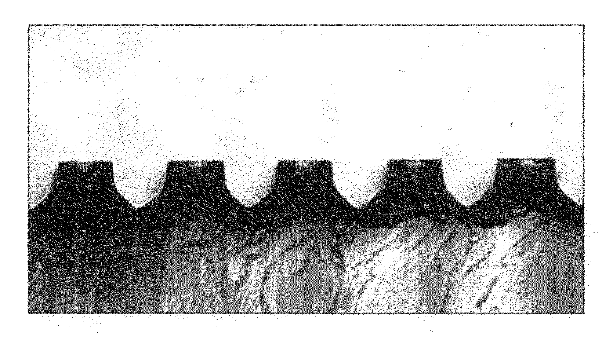
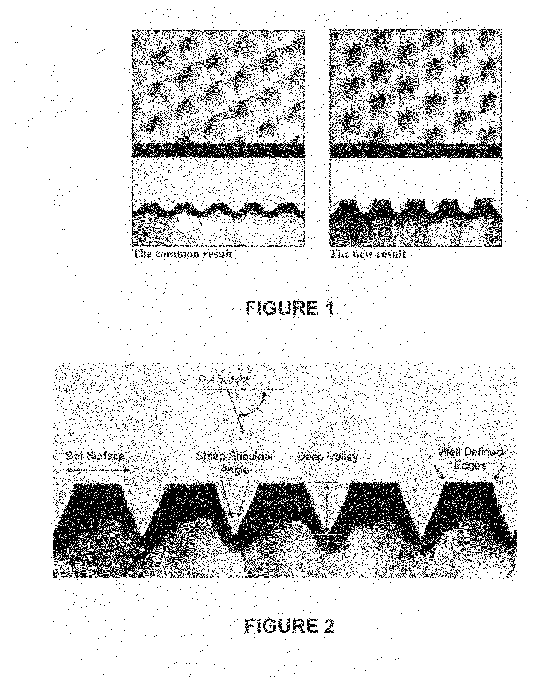
[0066]The inventors of the present invention have found that the shape and structure of a printing dot has a profound impact on the way it prints. Knowing this, one can manipulate the resultant shape of the printing dots to optimize printing by utilizing the printing methods described herein. FIG. 1 depicts a printing element with a plurality of dots demonstrating the unique dot / shoulder structure of the invention as compared to the dots of a printing element exposed without the benefit of this invention.

[0067]More particularly, the inventors of the present invention have found that a particular set of geometric characteristics define a flexo dot shape that yields superior printing performance, as shown in FIG. 2. The geometric parameters that characterize the optimum flexographic printing dot, especially in digital flexo printing, include:

[0068](1) planarity of the dot surface;

[0069](2) shoulder angle of the dot;

[0070](3) depth of relief between the dots; and

[0071](4) sharpness of ...


PUM

PropertyMeasurementUnit
shoulder angleaaaaaaaaaa

Abstract

A method of making a relief image printing element from a photosensitive printing blank is provided. A photosensitive printing blank with a laser ablatable layer disposed on at least one photocurable layer is ablated with a laser to create an in situ mask. The printing blank is then exposed to at least one source of actinic radiation through the in situ mask to selectively cross link and cure portions of the photocurable layer. Diffusion of air into the at least one photocurable layer is limited during the exposing step and preferably at least one of the type, power and incident angle of illumination of the at least one source of actinic radiation is altered during the exposure step. The resulting relief image comprises a plurality of dots and a dot shape of the plurality of dots that provide optimal print performance on various substrates, including corrugated board.

Description

CROSS-REFERENCE TO RELATED APPLICATIONS[0001]This application is a continuation-in-part of U.S. application Ser. No. 12 / 571,523, filed on Oct. 1, 2009, the subject matter of which is herein incorporated by reference in its entirety.FIELD OF THE INVENTION[0002]The present invention relates generally to a method of preparing a relief image flexographic printing element having an improved relief structure thereon, said improved relief structure including a plurality of relief dots that are configured for optimal printing.BACKGROUND OF THE INVENTION[0003]Flexography is a method of printing that is commonly used for high-volume runs. Flexography is employed for printing on a variety of substrates such as paper, paperboard stock, corrugated board, films, foils and laminates. Newspapers and grocery bags are prominent examples. Coarse surfaces and stretch films can be economically printed only by means of flexography. Flexographic printing plates are relief plates with image elements raised...

Claims


Application Information

Patent Timeline
Patent Type & Authority Applications(United States)
IPC IPC(8): B41N1/00B32B3/30
CPCB41C1/055B41M1/04B41N1/12Y10T428/24521G03F7/2012G03F7/202G03F7/09G03F7/201G03F7/26B41N1/06
Inventor RECCHIA, DAVID A.GOTSICK, TIMOTHY
Owner MACDERMID PRINTING SOLUTIONS
Why Eureka
Try Eureka