Apparatus and Method for Regulating the Output of a Plasma Electron Beam Source

a plasma electron beam and output technology, applied in the direction of light sources, electric discharge tubes, discharge tubes/lamp details, etc., can solve the problems of large fraction of electron current to the anode, uncontrolled output, and typical operation of devices, so as to achieve easy operation and greater control of the electron beam

Active Publication Date: 2011-04-07
THE UNITED STATES OF AMERICA AS REPRESENTED BY THE SECRETARY OF THE NAVY
View PDF5 Cites 33 Cited by
  • Summary
  • Abstract
  • Description
  • Claims
  • Application Information

AI Technical Summary

Benefits of technology

Thus, in accordance with the present invention, the electron beam can be easily turned on and off by opening and closing the switch between the control anode and the acceleration anode while continuously operating the plasma source and continuously applying voltage on the acceleration anode. With the apparatus and method in accordance with the presen...

Problems solved by technology

Thermionic (usually a hot filament) and field emission devices are commonly used to produce electron beams in low pressure applications; at pressures exceeding 10−4 Torr these devices typically begin to operate erratically and ultimately fail, often quickly, due to ion bombardment or exposure to reactive species such as oxygen or fluorine.
Furthermore, the accumulation of electron density sets the beam current in these devices.
In an electron beam device using a two-electrode plasma electron source, a large fraction of the electron current to the anode becomes the beam current, limited for practical reasons by the physical transparency of the anode which is usually a wire mesh.
This can lead to uncontrolled output, unsteady operation, component damage, or source failure.
Although a pulsed beam is ne...

Method used


Image

  • Apparatus and Method for Regulating the Output of a Plasma Electron Beam Source
  • Apparatus and Method for Regulating the Output of a Plasma Electron Beam Source
  • Apparatus and Method for Regulating the Output of a Plasma Electron Beam Source

Examples


example

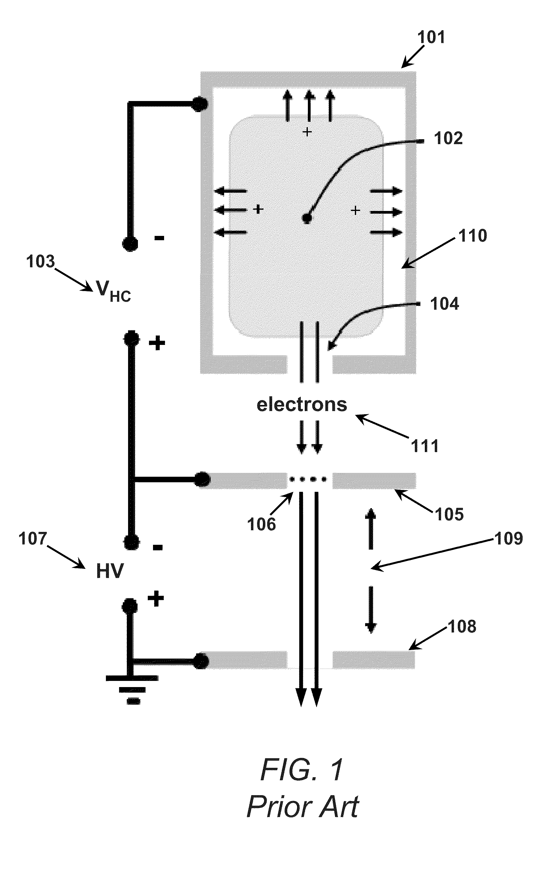
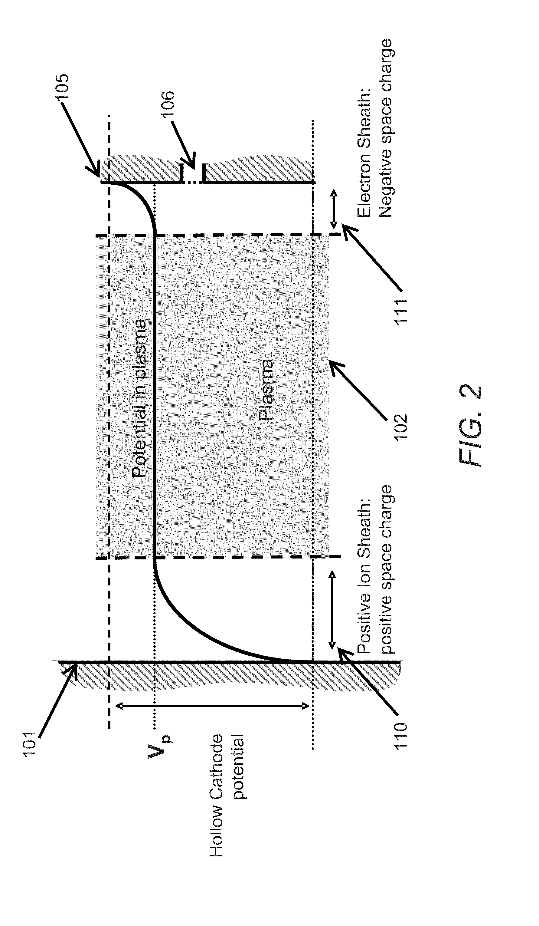
An exemplary embodiment of the present invention tested by the inventors hereof will now be described. In this exemplary embodiment, a 7.5 cm long cylindrical stainless steel hollow cathode with an interior cathode surface area (AK) of 50 cm2. Due to the applied magnetic field, the exit orifice surface area of the cathode determines the effective surface area of the acceleration anode (AA) relevant for the formation of the electron sheath. Thus, with the exit orifice area 0.03 cm2, the ratio of the effective area of the acceleration anode to the area of the hollow cathode was

AAAK=6×10⁻⁴.

Argon gas was fed into the back side of the cathode. For an argon discharge, the square root of the electron-to-ion mass ratio was

memi=3.7×10⁻³.

Thus, the criterion described above for an electron sheath to be present,

AAAK≤memi,

was satisfied.

The acceleration anode was located approximately 0.05 cm from the cathode exit and was made of stainless steel mesh (150 lines / in.), which provided a reasonably t...


PUM


Abstract

An apparatus and method for controlling electron flow within a plasma to produce a controlled electron beam is provided. A plasma is formed between a cathode and an acceleration anode. A control anode is connected to the plasma and to the acceleration anode via a switch. If the switch is open, the ions from the plasma flow to the cathode and plasma electrons flow to the acceleration anode. With the acceleration anode suitably transparent and negatively biased with a DC high voltage source, the electrons flowing from the plasma are accelerated to form an electron beam. If the switch is closed, the ions still flow to the cathode but the electrons flow to the control anode rather than the acceleration anode. Consequently, the electron beam is turned off, but the plasma is unaffected. By controlling the opening and closing of the switch, a controlled pulsed electron beam can be generated.

Description

TECHNICAL FIELDThe present invention relates to control of plasma-produced electron beams.BACKGROUNDElectron beams are used in wide variety of technological and scientific applications such as thin film deposition, electron beam welding, electron curing, waste management, ion thrusters, and plasma generators. Pulsed electron beams are often useful in such applications because they can provide improved performance compared to continuous beams. For example, in welding, instantaneous powers well in excess of average power can be achieved to increase the weld depth, while in the processing of materials, pulsed beams can drive surface chemistries while minimizing heating of the substrate, thus allowing the treatment of heat sensitive materials.The source of electrons for an electron beam device can be a thermionic emitter (a material heated until electrons “boil off”), a field emitter (high electric fields “rip” electrons out of a material), or a plasma (ionized gas). Most devices form e...

Claims


Application Information

Patent Timeline
IPC IPC(8): H05B31/26
CPCH01J15/02H01J3/025
Inventor WALTON, SCOTT G.COTHRAN, CHRISTOPHER D.FERNSLER, RICHARD F.MEGER, ROBERT A.AMATUCCI, WILLIAM E.
Owner THE UNITED STATES OF AMERICA AS REPRESENTED BY THE SECRETARY OF THE NAVY
Why Eureka
Try Eureka