
Frequency measurement method, frequency measurement device and apparatus equipped with frequency measurement device

Active Publication Date: 2011-04-07
SEIKO EPSON CORP
View PDF101 Cites 28 Cited by
  • Summary
  • Abstract
  • Description
  • Claims
  • Application Information

AI Technical Summary

Benefits of technology

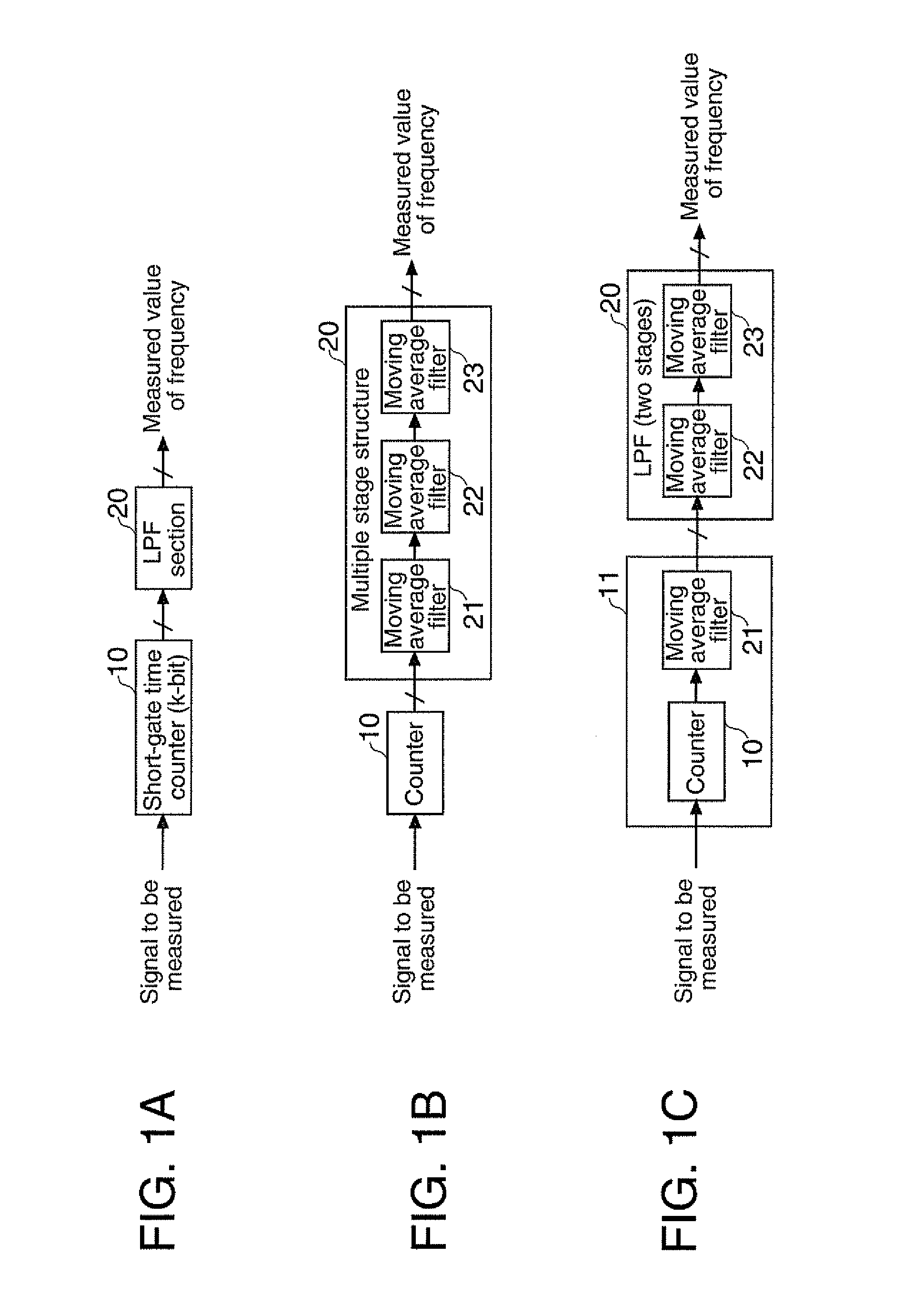
[0009]In accordance with an advantage of some aspects of the invention, it is possible to provide a counter (a frequency measurement device) of a short-gate time count method, wherein the structure of its low-pass filter section is simplified to achieve lower power consumption.
[0010]In accordance with another advantage of some aspects of the invention, it is possible to reduce noise generation that would likely occur, resulting from simplification of the filter structure of the low-pass filter section.
[0013]With the composition described above, the structure of the low-pass filter section in the frequency measurement device of a short-gate time count method can be simplified. By simplifying the circuit structure of the moving average filter and lowering the operation frequency of the circuit, the number of components and the power consumption can be reduced.
[0016]When downsampling is performed by a multiple-stage moving average filter, aliasing noise is generated. To prevent such aliasing noise, high frequency components need to be reduced to a substantially low level by inserting a low-pass filter before the downsampling. However, according to the structure of the invention, generation of aliasing noise that may occur in downsampling between the moving average filters can be avoided without providing an additional low-pass filter, such that the structure of the low-pass filter section can be simplified.
[0020]According to the structure of the invention, frequency measurement can be conducted, while generation of aliasing noise that may occur in the frequency measurement device using the short-gate time count method can be avoided, and the device structure can be simplified by means of downsampling.
[0021]The frequency measurement device described above is small in circuit scale and is readily mountable, and is therefore suitable to be used as a resonance frequency change type sensor. For example, such sensors include acceleration sensors and pressure sensors using quartz oscillators, QCM (Quartz Crystal Microbalance) devices and the like. For example, the frequency measurement device of the invention may be applied to a QCM odor sensor with crystal oscillators whose oscillation frequencies change by adhesion of odor substance to the crystal oscillators, whereby a multiple-channel odor sensor can be readily structured.

Problems solved by technology

However, the processing at the filter section needs addition and subtraction of multiple bits, such that the upper limit of sampling frequency in real time measurement is defined, mainly, by the processing power of the filter section.
To obtain a moving average filter with desired characteristics, it is necessary to structure a shift register with multiple bits in multiple stages and to operate such a shift register at high speed, resulting in a greater circuit scale and greater power consumption.
When downsampling is performed by a multiple-stage moving average filter, aliasing noise is generated.

Method used


Image

  • Frequency measurement method, frequency measurement device and apparatus equipped with frequency measurement device
  • Frequency measurement method, frequency measurement device and apparatus equipped with frequency measurement device
  • Frequency measurement method, frequency measurement device and apparatus equipped with frequency measurement device

Examples


first embodiment example

Comparison Example with Respect to First Embodiment Example

[0055]FIG. 5 shows, as a comparison example, a frequency measurement device in which the frequency measurement device shown in FIG. 4 is formed from an ordinary moving average filter (in non-gradual rate reducing operation). Portions corresponding to those shown in FIG. 4 are appended with the same reference numerals. The frequency measurement device of this example is also designed such that the short-gate time count is performed at 152 kHz (fs), and the cut-off frequency of the (three-stage) low-pass filter is set to be about 0.25 Hz.

[0056]According to the structure of the comparison example, the number of taps of the three-stage low-pass filter is 152 kHz÷0.25÷2=304 k taps, wherein 48 k taps are assigned to the first-stage register 113, 128 k taps to the second-stage register 222a, and 128 k taps to the third-stage register 232, and each of the stages is operated with a sampling frequency of 152 kHz (fs). According to the...

second embodiment example

Comparison Example with Respect to Second Embodiment Example

[0062]FIG. 7 shows, as a comparison example, a frequency measurement device in which the frequency measurement device shown in FIG. 6 is formed from an ordinary moving average filter (in non-gradual rate reducing operation). Portions corresponding to those shown in FIG. 6 are appended with the same reference numerals. The frequency measurement device of this example is also designed such that the short-gate time count is performed at 4760 kHz (fs), and the cut-off frequency of the (three-stage) low-pass filter is set to be about 0.77 Hz, like the second embodiment example.

[0063]According to this comparison example, the count filter section 11 is composed of a binary signal (bit stream) processing circuit, like the circuit shown in FIG. 6. The second-stage moving average filter 22 is formed from a 2048-stage shift register 222b that delays the 1-bit output of the count filter section 11 in synchronism with a sampling clock (...

third embodiment example

[0072]Next, referring to FIGS. 10 through 14, examples of methods for improving the S / N ratio of the frequency measurement device by appropriately adjusting (tuning) the tap number of the multiple-stage moving average filter and downsampling frequency of the frequency measurement device that combines the short-gate time count method and downsampling.

[0073]In accordance with the third embodiment example, in the frequency measurement device using the short-gate time count method described in the first and second embodiment examples (having a low-pass filter composed of moving average filters in multiple stages wherein sampling frequencies for acquiring data at the moving average filters at the respective stages are set to gradually lower from the first stage toward the last stage), in downsampling between two forward and rear moving average filters, the number of data delay stages in the moving average filter in the forward stage or the sampling frequency in the moving average filter ...


PUM


Abstract

A frequency measurement device includes: a counter section that counts a supplied pulse stream signal to be measured at a predetermined time interval and outputs a stream of count values corresponding to the frequency of the signal to be measured; and a low-pass filter section that performs a filtering process on the stream of count values, the low-pass filter section including moving average filters in multiple stages, and an output of at least one moving average filter among the moving average filters in multiple stages is downsampled.

Description

[0001]The present application claims a priority based on Japanese Patent Application No. 2009-232501 filed on Oct. 6, 2009, the contents of which are incorporated herein by reference.BACKGROUND[0002]1. Technical Field[0003]The present invention relates to frequency measurement devices and, more particularly, to improvements of a frequency measurement device that is capable of measuring an absolute frequency, using a frequency measurement device that counts a signal to be measured for a predetermined time, and removes high frequency components from a stream of counted values thereby detecting a frequency change component.[0004]2. Related Art[0005]As frequency measurement methods, a direct count method that counts pulses passing within a predetermined gate time (see, for example, JP-A-2001-119291 (Patent Document 1)), a reciprocal method that accurately measures a pulse period and obtains a frequency from its time reciprocal (see, for example, JP-A-05-172861 (Patent Document 2)), and ...

Claims


Application Information

Patent Timeline
IPC IPC(8): G01R23/10G01R23/00
CPCG01R23/10G01N33/0031
Inventor TODOROKIHARA, MASAYOSHI
Owner SEIKO EPSON CORP
Learn More