
Construction panel

a construction panel and construction technology, applied in the field of construction panels, can solve the problems of high amount of cosub>2 /sub>emitted through their manufacture, detrimental environmental effects, etc., and achieve the effects of reducing delays and construction project duration, easy recycling, and high quality

Inactive Publication Date: 2011-04-21
MODCELL
View PDF7 Cites 5 Cited by
  • Summary
  • Abstract
  • Description
  • Claims
  • Application Information

AI Technical Summary

Benefits of technology

Advantageously, a construction element according to the invention provides a modular system for creating a building using cellulosic material as a cladding and insulating material. In addition, since cereal crops sequester carbon dioxide during their growth, the use of straw within a construction element and preserving it for the life of a building offers a means of reducing carbon dioxide levels. A typical 3.2×3 m panel according to the invention has the atmospheric equivalent of 595 kg of CO2 locked inside it. In addition, the inclusion of compression of the straw and of the stabilising element(s) results in a construction element which not only provides good insulation but is also stable against flexing as the result of weather forces such as wind.
Bracing elements are placed across the corners of the frame to increase the stiffness of the structure and to maintain the shape and dimensions of the rectangle. A render is applied to the cut ends of the straw stems and extends across the whole area of the frame, such that the final product is a pre-fabricated construction panel, ready for use in the construction of a building.
The method may further comprise the step of attaching at least one bracing element to the frame, for example across a corner of the frame to provide additional stiffness and to ensure that the shape and dimensions of the frame are maintained. The method preferably further comprises the step of applying a render to an exposed face of at least one cellulose bale. For example, where the construction element is a panel, render may be applied across all exposed straw such that the end product is a panel with both large faces fully rendered. Advantageously, the use of bales which have been cut such that cut ends of the straw stalks are exposed improved the binding of render to the surface of the straw bales.
The invention represents an innovative, high quality, external cladding system for buildings using straw bales, an agricultural by-product, together with timber and hydraulic lime. Advantageously, the construction element according to the invention may be manufactured away from the final building construction site, so that the elements are provided to the construction site in a pre-fabricated form, reducing delays and construction project duration. The cladding system is suitable for a wide range of low and medium rise buildings. Development of this technology will provide building elements using resource efficient renewable insulation materials that are capable of storing, throughout their life cycle, significant quantities of CO2 sequestrated from the atmosphere. Straw bales are locally available at most locations in the UK, non-toxic and easily recycled, as animal bedding, or disposed at the end of their life cycle. The construction elements of the invention can be constructed locally at “flying factories”, given the simple nature of the construction and the local availability of straw bales; such local construction further minimises the impact of a building project on the environment, by reducing the need to transport building components over large distances. Using plant fibre materials will replace other currently widely used materials, such as rigid polyurethane and mineral fibre insulation products, which rely on essentially non-renewable resources and often involve industrial processes that have potential to damage the environment (e.g. fossil fuel extraction), as well as reduce the quantity of waste insulation materials sent to landfill on end use.

Problems solved by technology

Thinner wall constructions are available but the type of insulation used, such as phenolic foams or expanded polystyrene foamed glass, all have detrimental environmental effects and the amount of CO2 emitted through their manufacture is high.

Method used


Image

  • Construction panel
  • Construction panel
  • Construction panel

Examples


Embodiment Construction

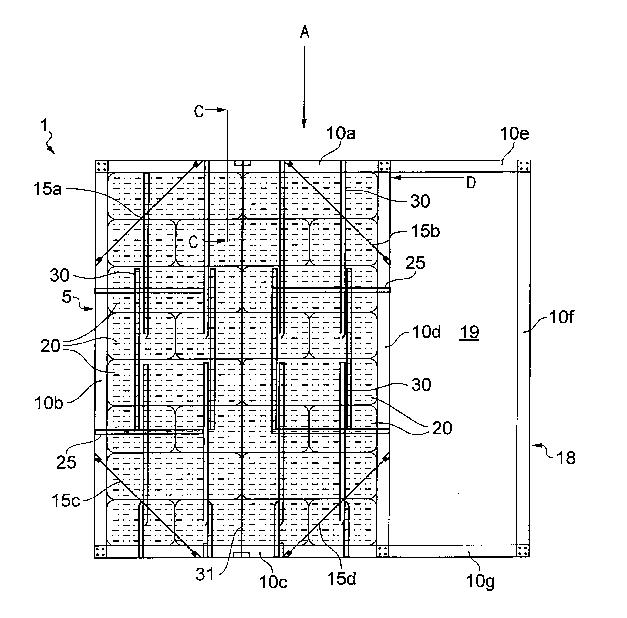
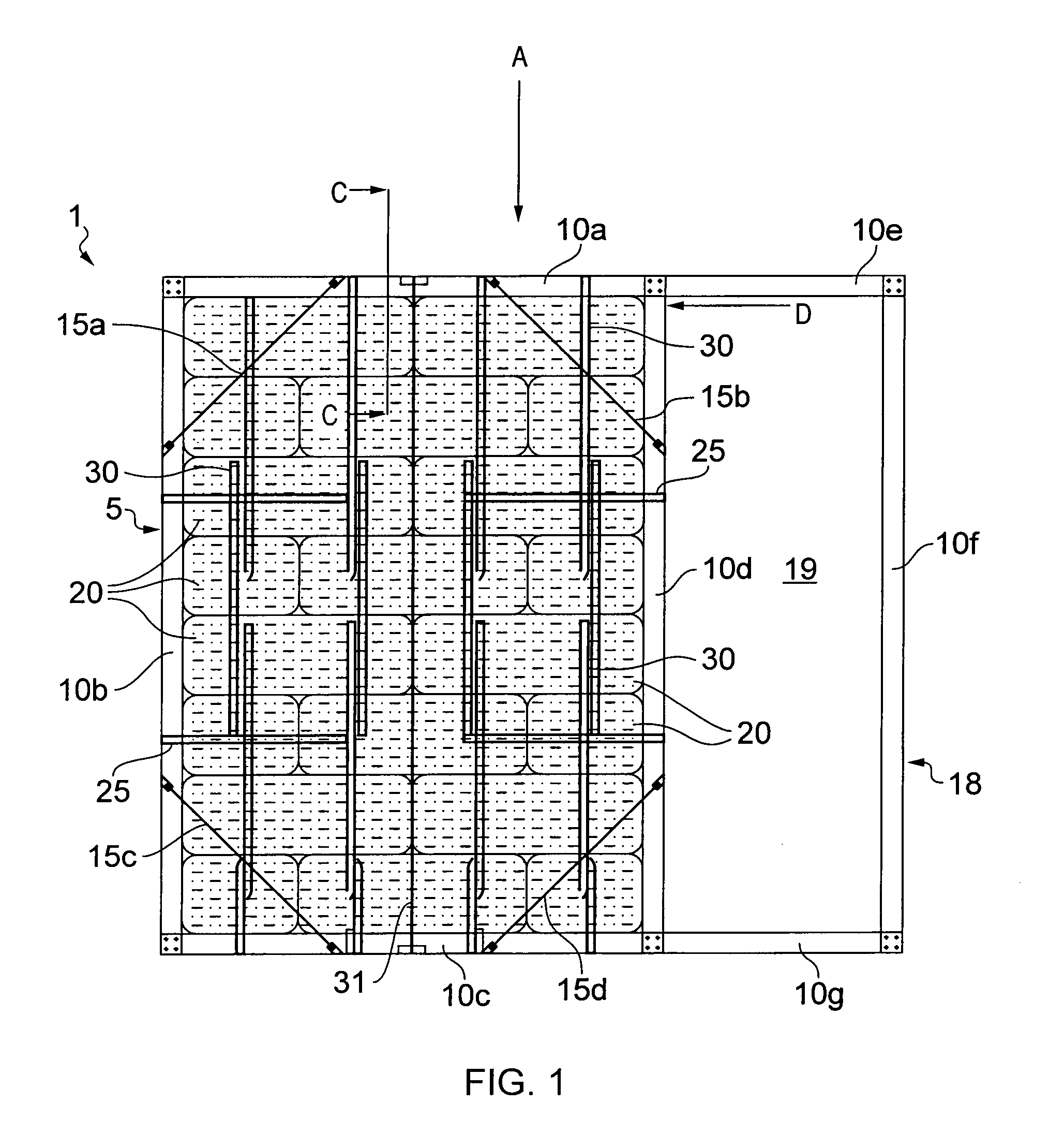
FIG. 1 shows a building panel 1 having a timber frame 5, with four sides, 10a, 10b, 10c and 10d. The frame is braced with corner braces 15a, 15b, 15c and 15d which serve to stiffen the structure and maintain the corners at an angle of 90°. A secondary frame 18 formed by secondary frame sides 10e, 10f and 10g is also shown; these frame sides, along with side 10d of the frame 5, form aperture 19. Sides 10e and 10g may, in fact, be extensions of sides 10a and 10c, respectively, such that, for example, elements 10a and 10e are a single, unitary element. The secondary frame may be used as, for example, a window frame or a door frame, with the aperture 19 being covered by a window or a door, respectively.

A plurality of straw bales 20 are positioned in eight layers within the frame, in a running bond arrangement. Timber dowels 25 are inserted through the bales within a single layer, to hold them in the correct position. Dowels 30 may also be inserted through the layers of bales, to hold th...


PUM

PropertyMeasurementUnit
densityaaaaaaaaaa
thickaaaaaaaaaa
thickaaaaaaaaaa

Abstract

There is provided a construction element comprising a frame (5) and a plurality of cellulose bales (20), characterised in that the construction element further comprises at least one stabilising element (30) and in that the plurality of cellulose bales (20) is compressed. There is further provided a method of manufacture of such a construction element.

Description

FIELD OF THE INVENTIONThe invention relates to the area of building construction, providing pre-fabricated panels for use in construction of a building. In particular, the invention relates to panels which include straw bales in their structure.BACKGROUNDOver recent years, there has been increasing focus on the impact of construction projects on the global environment, in terms of the methods and materials used in construction and in terms of the efficiency of the buildings created. For example, improved thermal insulation to minimise heat energy loss from buildings is widely recognised as essential to achieving government targets for greenhouse gas emission reductions (DTI Energy White Paper—Our energy future, creating a low carbon economy, 2003). The United Kingdom government has set the target for all new housing in the UK to be zero carbon dioxide emitting by the year 2016. The means by which this will be regulated is called the Code for Sustainable Homes, zero carbon is describ...

Claims


Application Information

Patent Timeline
Patent Type & Authority Applications(United States)
IPC IPC(8): E04C2/18E04C2/16E04C2/10B29C33/38B29C43/18
CPCE04B1/3555E04C2/386E04C2/18E04B1/12E04B2001/745
Inventor WHITE, CRAIGMANDER, TIMOTHY
Owner MODCELL
Learn More