System for and method of degrading or analysing the performance of an internal combustion engine

a technology of internal combustion engine and performance analysis, which is applied in the direction of electrical control, structural/machine measurement, instruments, etc., can solve the problems of deactivation, simple disconnect, and gradual reduction of fuel supply

Inactive Publication Date: 2011-04-21
MOBILIZER
View PDF14 Cites 6 Cited by
  • Summary
  • Abstract
  • Description
  • Claims
  • Application Information

AI Technical Summary

Benefits of technology

[0021]The Hall Effect current sensor and optically coupled MOSFET switching block may be connected such as to provide a low-resistance electrically conductive path completing a circuit between the PCM and the injector.
[0022]The system may include an opto-coupler connected in parallel to the optically coupled MOSFET switching block to detect any potential difference during an “off” state of the switching block. This is required in combination with the current sensor, which, of course, turns off when the MOSFET is switched off by the microprocessor. Indeed, the pulse length intended by the vehicle's P

Problems solved by technology

Alternatively, use of the vehicle without the proper key might trigger gradual reduction in fuel supply

Method used


Image

  • System for and method of degrading or analysing the performance of an internal combustion engine
  • System for and method of degrading or analysing the performance of an internal combustion engine

Examples


Embodiment Construction

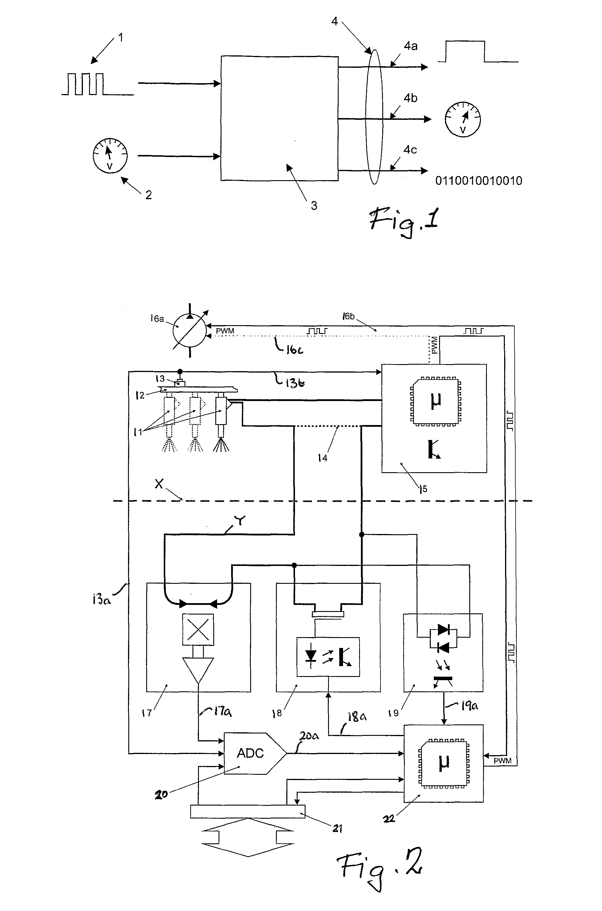
[0029]Referring now to FIG. 1, the system employed by the present invention is illustrated diagrammatically at 3 and is adapted to receive signals monitoring the injection pulses 1 applied to each injector from the engine management computer (15 in FIG. 2). These may consist of individual pulses or groups of pulses per engine cylinder combustion stroke. The total injection duration is calculated in system 3 and multiplied by a relative voltage 2 representing the fuel pressure derived from a fuel supply pump (16a in FIG. 2). Output data is generated at 4 representing the total fuel quantity delivered to the combustion chamber, and this may consist of one or more of an individual pulse 4a, per combustion, of variable pulse width, a variable voltage / current analogue output 4b, a digital output 4c, or a combination of all three.

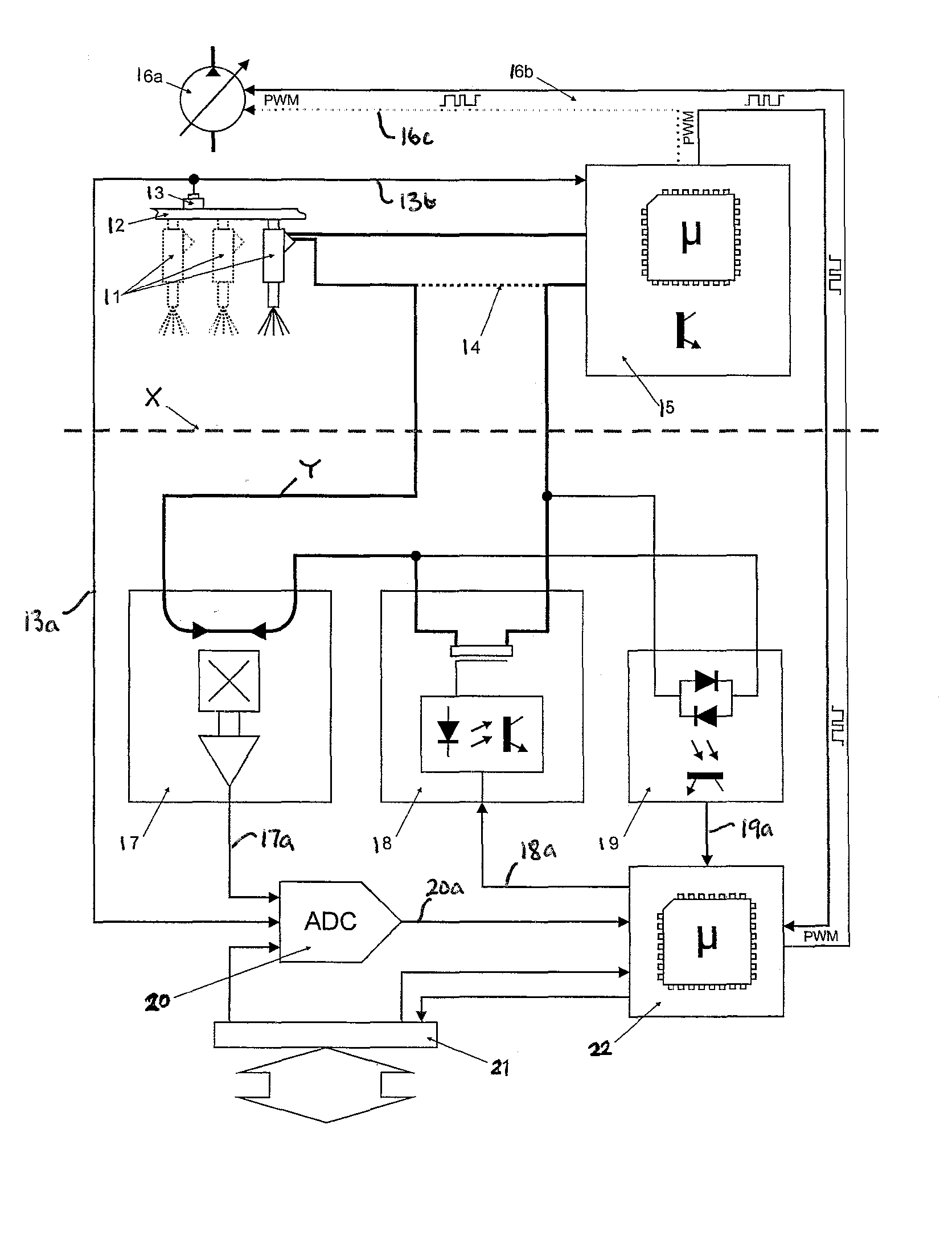
[0030]Referring now to FIG. 2, a dotted line X represents a point of connection of the system illustrated below the line X, to an engine management computer or p...


PUM


Abstract

A degrader and a diagnostic kit for an electronically-controlled fuel-injected internal combustion engine includes means adapted to interrupt a control signal from an engine management computer or powertrain control module (PCM) (15) to a fuel injector (11). It comprises a current sensor (17), adapted to measure the duration of a pulsed supply of fuel to the injector, a switching block (18) to interrupt the supply if required, and a microprocessor (22) to actuate the switching block and to produce a signal which may be used to control injection of fuel into the engine.

Description

[0001]This invention is concerned with a system for, and method of, degrading the performance of an internal combustion engine, potentially leading to its total immobilisation. The invention also relates to a system for diagnosing engine performance. In general terms both proposals revolve around determining, and potentially interfering with, the amount of fuel injected into diesel or petrol engines. This involves measuring and, as appropriate, controlling the fuel supplied to the engine. The system is also useful in controlling the performance or efficiency of the engine.BACKGROUND[0002]Since the introduction of electronic fuel injection for the supply of fuel to engines, many systems have been developed to meet the requirements of each fuel type and to address the demands of improved performance, efficiency and lower exhaust emissions. While each of the known systems shares the same basic principal of injecting fuel into an engine via an electronically controlled solenoid valve kn...

Claims


Application Information

Patent Timeline
IPC IPC(8): G01M15/04B60R25/042
CPCB60R25/042F02D41/28F02D41/3082Y02T10/44F02D2041/228F02D2200/501F02D41/406Y02T10/40
Inventor HOWARTH, MARK VINCENTZYLA, EDWARD CHRISTOPHER
Owner MOBILIZER
Why Eureka
Try Eureka