
Methods of depositing discrete hydroxyapatite regions on medical implants

a technology of hydroxyapatite and medical implants, applied in the field of medical implants, can solve problems such as neogagging its

Inactive Publication Date: 2011-04-21
BIOMET MFG CORP
View PDF52 Cites 14 Cited by
  • Summary
  • Abstract
  • Description
  • Claims
  • Application Information

AI Technical Summary

Benefits of technology

[0001]The present technology relates to medical implants having discrete regions of a calcium phosphate (e.g., hydroxyapatite), and methods of their manufacture. In the growing field of medical devices, there is a continued need to provide lightweight orthopedic implants having enhanced in-growth capability. It is known that the time between in-growth of a metallic implant until the full mechanical loadability is achieved can be reduced if the implant has been coated with a calcium phosphate phase (CPP), such as hydroxyapatite.
[0002]Hydroxyapatite is a biocompatible material similar in composition to the mineral content of natural bone. As a result, hydroxyapatite coatings on medical orthopedic implants can enhance the implant's osteoconductive potential, among other things. CPP coatings can be deposited onto electroconductive, or metal substrates using solution-based techniques, such as electrochemical deposition or sol-gel deposition. One advantage of using such deposition processes is that they are not “line of sight” processes and thus can provide a complete coating coverage of complex shaped substrates. With the use of implants having nano-scale texturing, however, such deposition processes can be disadvantageous in that the coating may be applied over the nano-scale texturing, thereby negating its affect. Accordingly, there remains a need to provide methods for using electrochemical deposition techniques to provide discrete regions of CPP, including hydroxyapatite.SUMMARY

Problems solved by technology

With the use of implants having nano-scale texturing, however, such deposition processes can be disadvantageous in that the coating may be applied over the nano-scale texturing, thereby negating its affect.

Method used


Image

  • Methods of depositing discrete hydroxyapatite regions on medical implants
  • Methods of depositing discrete hydroxyapatite regions on medical implants
  • Methods of depositing discrete hydroxyapatite regions on medical implants

Examples


example 1

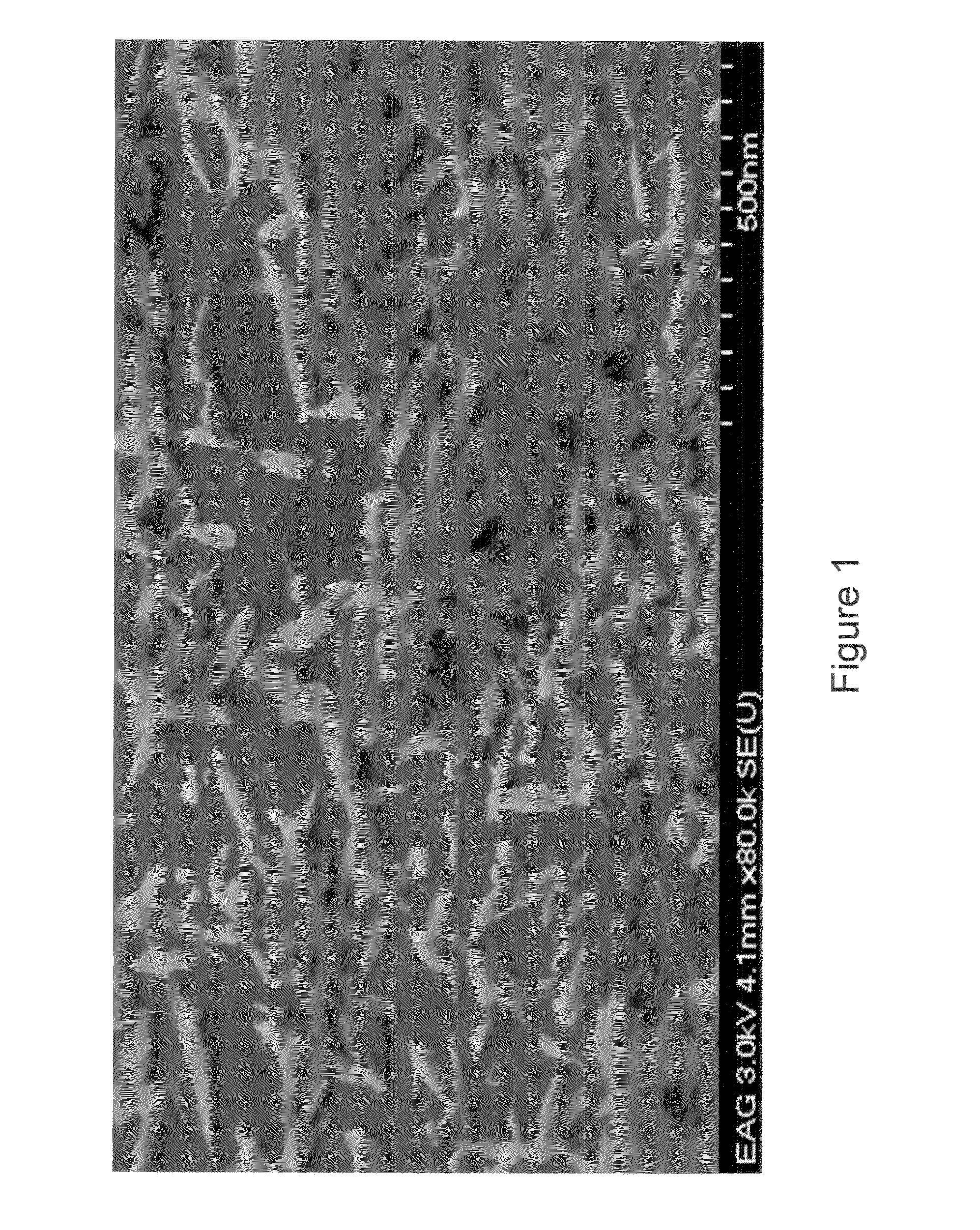
[0035]A disc of Ti6Al4V having a radius of about 0.5 inches and a thickness of 0.25 inches is prepared with a smooth machine finish, cleaned in an ultrasonic bath, and rinsed with distilled water. The thickness portion is masked and the disc sample is placed into an electrolyte solution at ambient temperature including 150 ml each of a stock solution of CaCl2 and NH4H2PO4 in concentrations of 33 mM and 20 mM, respectively. Deionized water is added providing a 3 L total volume solution having a final concentration of 1.67 mM calcium ions and 1.0 mM phosphate ions. The pH is adjusted to 5.1 using hydrochloric acid.

[0036]After connection to a potentiostat, electrochemical deposition is carried out by means of galvanostatic polarization under cathodic current flow at a current density of about 40 mA / cm2 in order to provide a high flux of ions toward the cathode. After a deposition time of about 2.5 minutes, the cathodic polarization is complete and the sample is removed and rinsed with ...

example 2

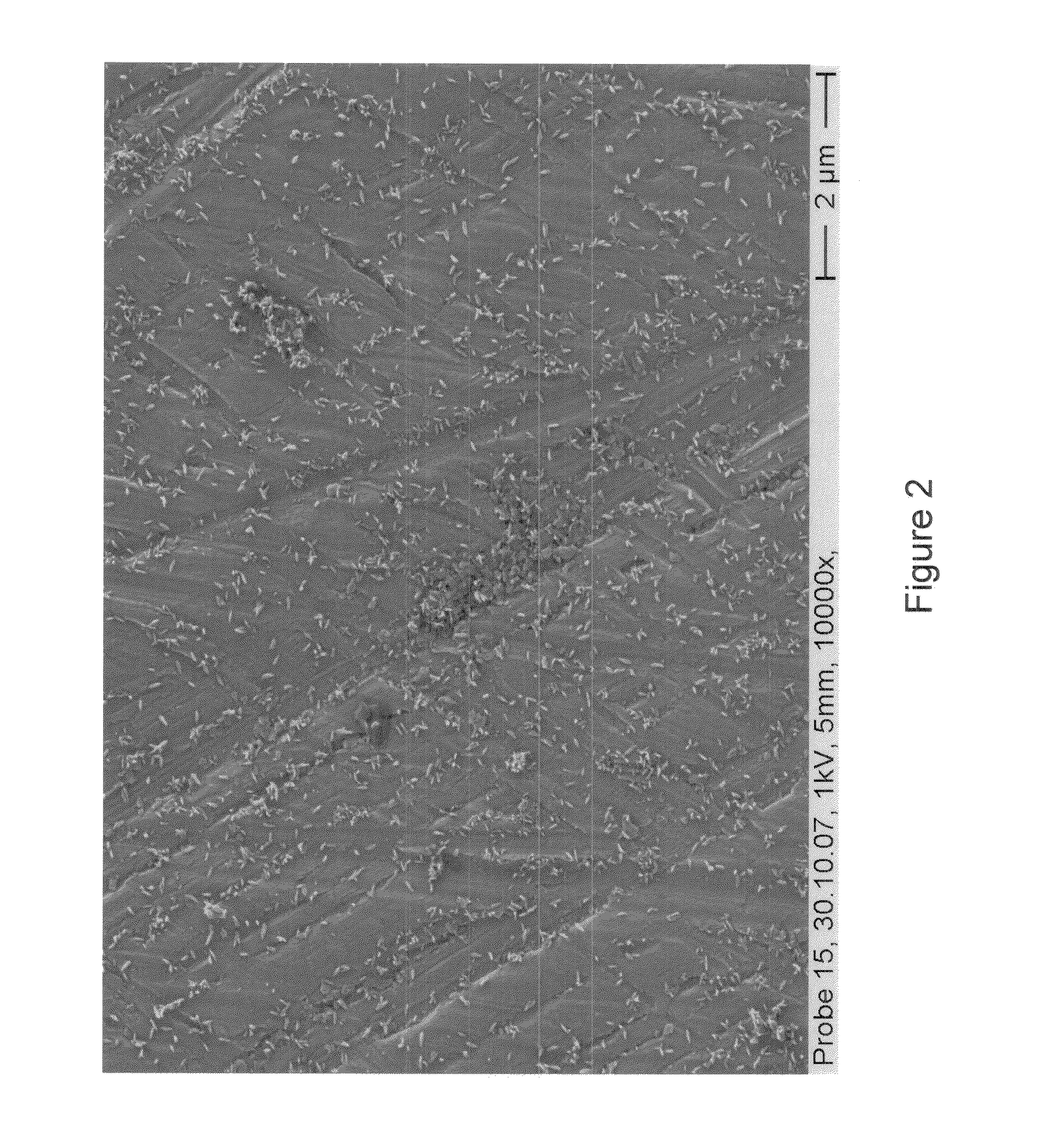
[0037]A disc of Ti6Al4V is prepared as in Example 1. The disc sample is placed into an electrolyte solution at ambient temperature including 15 ml each of a stock solution of CaCl2 and NH4H2PO4 in concentrations of 33 mM and 20 mM, respectively. Deionized water is added providing a 3 L total volume solution having a final concentration of 0.167 mM calcium ions and 0.1 mM phosphate ions. The pH is adjusted to 6.4 using ammonium hydroxide.

[0038]After connection to a potentiostat, electrochemical deposition is carried out by means of galvanostatic polarization under cathodic current flow at a current density of about 20 mA / cm2 in order to provide a high flux of ions toward the cathode. After a deposition time of about 10 minutes, the cathodic polarization is complete and the sample is removed and rinsed with deionized water. Electron microscopic examination reveals a plurality of discrete but homogenous regions of CPP having needle like morphology as shown in FIG. 2. Further IR-spectro...

example 3

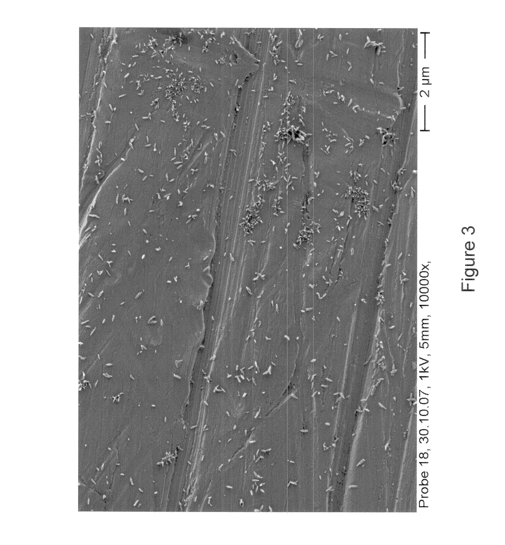
[0039]A disc of Ti6Al4V is prepared as in Example 1. The disc sample is placed into an electrolyte solution at ambient temperature including 15 ml each of a stock solution of CaCl2 and NH4H2PO4 in concentrations of 33 mM and 20 mM, respectively. Deionized water is added providing a 3 L total volume solution having a final concentration of 0.167 mM calcium ions and 0.1 mM phosphate ions. The pH is adjusted to 6.4 using ammonium hydroxide.

[0040]After connection to a potentiostat, electrochemical deposition is carried out by means of galvanostatic polarization under cathodic current flow at a current density of about 30 mA / cm2 in order to provide a high flux of ions toward the cathode. After a deposition time of about 10 minutes, the cathodic polarization is complete and the sample is removed and rinsed with deionized water. Electron microscopic examination reveals a plurality of discrete but homogenous regions of CPP having needle like morphology as shown in FIG. 3. Further IR-spectro...


PUM

PropertyMeasurementUnit
constant current densityaaaaaaaaaa
current densityaaaaaaaaaa

Abstract

A method for electrochemically depositing discrete regions of calcium phosphate onto a medical implant. The method includes providing an implant including at least one area having a metallic surface. At least a portion of the metallic surface is contacted with an electrolyte solution comprising calcium ions and phosphate ions. The metallic surface is used as a cathode, and an electrical potential is applied between the cathode and the electrolyte solution. The electrical potential is applied with a constant current density of from about 10 to about 50 mA / cm2 for a period of time of from about 1 to about 20 minutes. A plurality of discrete regions of needle-shaped hydroxyapatite crystals are electrochemically deposited onto the metallic surface.

Description

INTRODUCTION[0001]The present technology relates to medical implants having discrete regions of a calcium phosphate (e.g., hydroxyapatite), and methods of their manufacture. In the growing field of medical devices, there is a continued need to provide lightweight orthopedic implants having enhanced in-growth capability. It is known that the time between in-growth of a metallic implant until the full mechanical loadability is achieved can be reduced if the implant has been coated with a calcium phosphate phase (CPP), such as hydroxyapatite.[0002]Hydroxyapatite is a biocompatible material similar in composition to the mineral content of natural bone. As a result, hydroxyapatite coatings on medical orthopedic implants can enhance the implant's osteoconductive potential, among other things. CPP coatings can be deposited onto electroconductive, or metal substrates using solution-based techniques, such as electrochemical deposition or sol-gel deposition. One advantage of using such deposi...

Claims


Application Information

Patent Timeline
Patent Type & Authority Applications(United States)
IPC IPC(8): C25D5/54C25D9/04C25D5/34
CPCC25D5/18C25D9/08C25D5/48C25D5/617
Inventor GUPTA, GAUTAMSEWING, ANDREAS
Owner BIOMET MFG CORP
Learn More