
Carbon dioxide reforming process

Active Publication Date: 2011-04-21
MURATA MFG CO LTD
View PDF6 Cites 28 Cited by
  • Summary
  • Abstract
  • Description
  • Claims
  • Application Information

AI Technical Summary

Benefits of technology

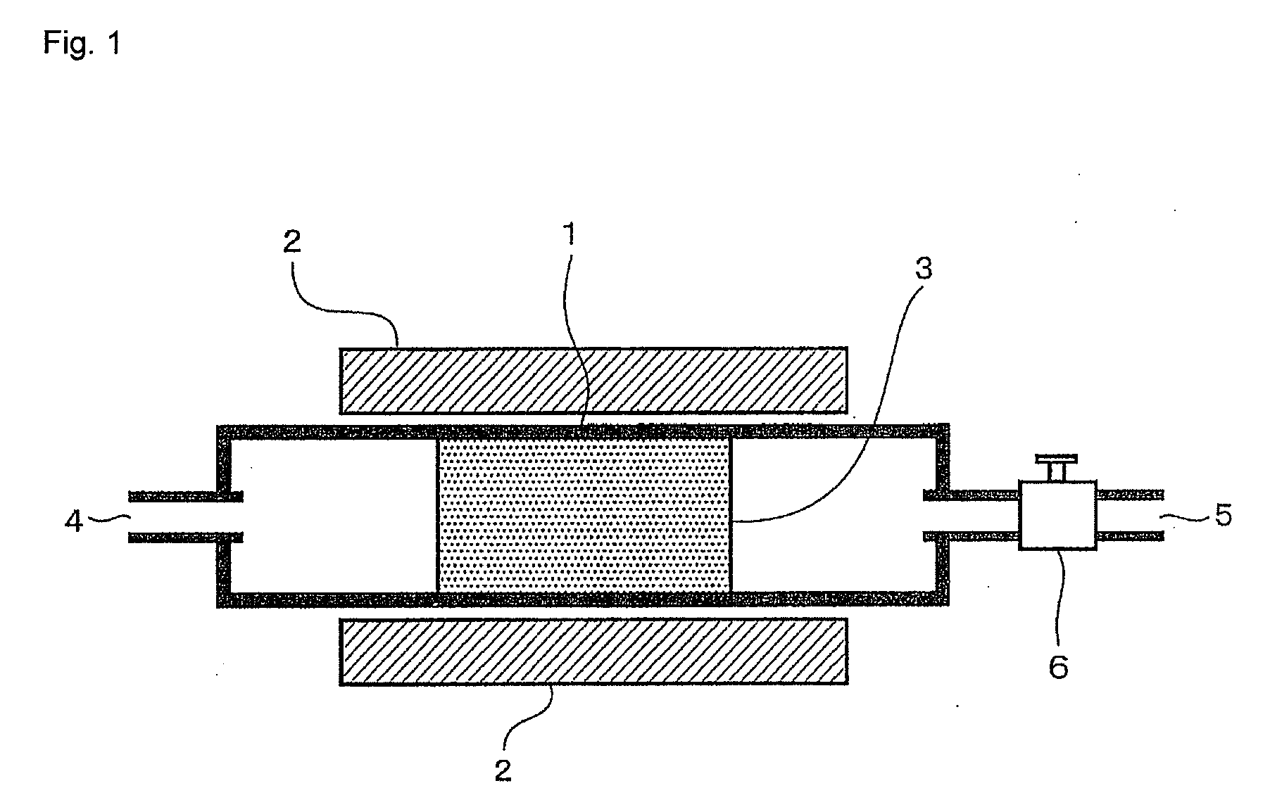
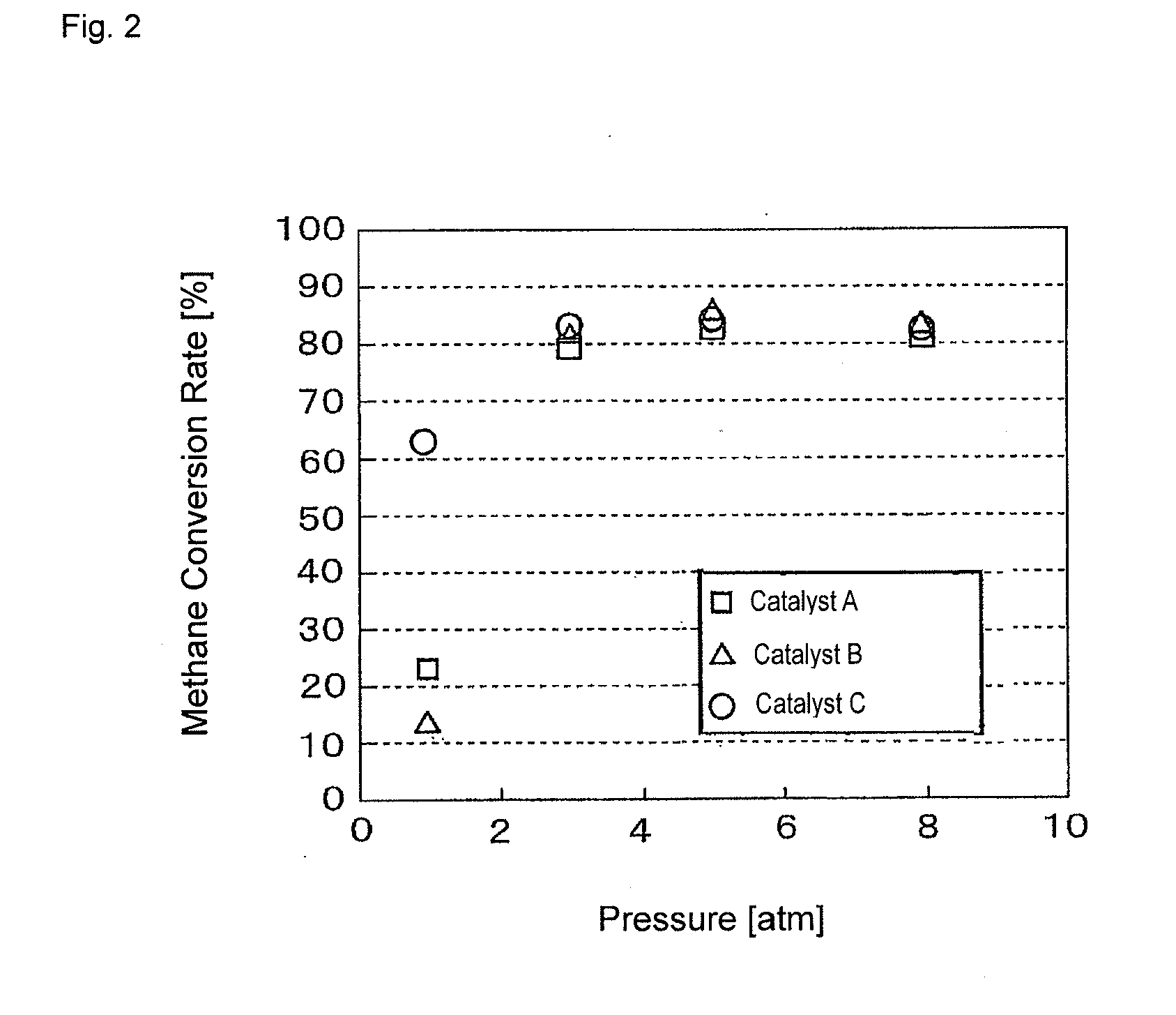
[0018]The carbon dioxide reforming process of the present invention performs carbon dioxide reforming of a hydrocarbon feedstock gas using a carbon dioxide reforming catalyst containing a carbonate of at least one alkaline earth metal selected from the group consisting of Ca, Sr, and Ba, a catalytic metal promoting the decomposition reaction of a hydrocarbon feedstock gas, and a complex oxide containing at least one component selected from the group consisting of Ti, Al, Zr, Fe, W, and Mo and at least one alkaline earth metal selected from the group consisting of Ca, Sr, and Ba. Therefore, even when the operation of carbon dioxide reforming is performed under pressure conditions of 3 atmospheres (0.304 MPa) or more, carbon deposition in the reforming step is suppressed, and carbon dioxide reforming can be efficiently performed.
[0019]That is, a hydrocarbon feedstock gas is subjected to carbon dioxide reforming under pressurized conditions using the catalyst described above, whereby the hydrocarbon can be reformed into carbon dioxide and hydrogen, while suppressing carbon deposition, more efficiently than the case of performing carbon dioxide reforming under atmospheric pressure conditions.
[0020]According to

Problems solved by technology

In addition, despite being generated in the technical fields of petroleum refining, petroleum chemistry, and the like, various hydrocarbon gases cannot be always efficiently utilized as feedstock gases for various substances, and a method for converting hydrocarbon gases into more effective substances has been desired.
However, carbon deposition is likely to occur on the catalyst when the catalyst in which nickel, ruthenium, or rhodium is supported on a carrier such as alumina or silica described above is used, and there is a problem in that the surface of the catalyst is covered by the deposited carbon and activity is decreased, and that the reaction vessel becomes clogged by the blocking of the space between catalyst grains.

Method used


Image

  • Carbon dioxide reforming process
  • Carbon dioxide reforming process

Examples


example 1

[0036]As the catalysts used in the carbon dioxide reforming process of the present invention, the following carbon dioxide reforming catalysts A, B, and C were prepared.

Carbon Dioxide Reforming Catalyst A

[0037]BaCO3 and TiO2 were weighed so as to have a molar ratio of 2.0:1.0, and further, NiO was added thereto and mixed therewith so as to be in an amount of 2% by weight.

[0038]Next, a binder was added to this mixture, and the resulting mixture was pelletized into spherical pellets having a diameter of 2 to 5 mm. The resulting granular pellets were fired under the conditions of 1,100° C. for 1 hour in the air, thereby obtaining a mixture of Ba2TiO4 and NiO.

[0039]This mixture was fired under the conditions of 700° C. for 1 hour in an air flow of 20% CO2 and 80% N2, thereby obtaining carbon dioxide reforming catalyst A with a molar ratio of BaCO3 and BaTiO3 of 1.0:1.0, and which was a mixture of BaCO3, BaTiO3, and NiO.

[0040]From the weight change of the sample before and after the firi...


PUM

PropertyMeasurementUnit
Pressureaaaaaaaaaa
Pressureaaaaaaaaaa
Fractionaaaaaaaaaa

Abstract

A synthetic gas containing hydrogen and carbon monoxide is efficiently obtained by reacting a hydrocarbon feedstock gas with carbon dioxide under pressure, while suppressing carbon deposition. The pressure is preferably 3 atmospheres (0.304 MPa), and used is a carbon dioxide reforming catalyst that contains at least one alkaline earth metal carbonate a catalytic metal promoting the decomposition reaction of a hydrocarbon feedstock gas, at least one alkaline earth metal selected from the group consisting of Ca, Sr, and Ba, and a complex oxide containing at least one component selected from the group consisting of Ti, Al, Zr, Fe, W, and Mo, such as ATiO3, AAl2O4, AZrO3, AFe2O4, A3W2O9, A2WO5, or AMoO4, where A is at least one of Ca, Sr, and Ba.

Description

[0001]This is a continuation-in-part of PCT / JP2009 / 060426, filed Jun. 8, 2009, the contents of which are hereby incorporated herein by reference.TECHNICAL FIELD[0002]The present invention relates to a carbon dioxide reforming process, and specifically, a carbon dioxide reforming process used for reforming a hydrocarbon feedstock gas in the presence of carbon dioxide to obtain a synthetic gas containing hydrogen and carbon monoxide.BACKGROUND ART[0003]Since carbon dioxide is a major cause of global warming, a reduction in its discharge and effective utilization of it have been regarded as urgent requirements in recent years.[0004]In addition, despite being generated in the technical fields of petroleum refining, petroleum chemistry, and the like, various hydrocarbon gases cannot be always efficiently utilized as feedstock gases for various substances, and a method for converting hydrocarbon gases into more effective substances has been desired.[0005]Under the circumstances described ...

Claims


Application Information

Patent Timeline
IPC IPC(8): C01B3/00
CPCB01J21/063B01J23/78C01B3/40C01B2203/0238Y02E60/324C01B2203/1058C01B2203/1064C01B2203/1082C01B2203/1047Y02P20/52Y02E60/32
Inventor SATO, HIDETOSAITO, YOSHINORI
Owner MURATA MFG CO LTD
Learn More