Piezoelectric resonator element, piezoelectric resonator, and acceleration sensor

a piezoelectric resonator and resonator technology, applied in the direction of piezoelectric/electrostrictive device details, instruments, device details, etc., can solve the problem of not being able to obtain accurate acceleration detection results in the y-axis direction, and achieve the effect of reducing the sensitivity of other axes

Inactive Publication Date: 2011-04-21
SEIKO EPSON CORP
View PDF8 Cites 4 Cited by
  • Summary
  • Abstract
  • Description
  • Claims
  • Application Information

AI Technical Summary

Benefits of technology

[0010]An advantage of the present invention is to provide a piezoelectric resonator element in which the rigidities of both faces thereof with respect to the flexural vibration described above are balanced and sensitivity in other axis is reduced; a piezoelectric resonator provided with the piezoelectric resonator element; and an acceleration sensor provided with the same.
[0011]The above advantage can be attained by the following aspects of the invention.
[0012]A piezoelectric resonator element according to a first aspect of the invention includes: a resonating arm extending in a first direction and cantilever-supported; a base portion cantilever-supporting the resonating arm; and an excitation electrode exciting the resonating arm to perform flexural vibration in a second direction that is orthogonal to the first direction. In the resonator element, the resonating arm includes an adjusting part for the rigidity with respect to a bend in a third direction that is orthogonal to the first direction and the second direction.
[0013]In the piezoelectric resonator element composed of a piezoelectric plate, rigidities with respect to a bending stress and the like on faces are sometimes different from each other due to the anisotropy of the plate. If such piezoelectric resonator element is excited to perform flexural vibration by the excitation electrode, the vibration includes not only a component in a predetermined vibrating direction but also a component of vibration in a direction that is orthogonal to the predetermined vibrating direction. Therefore, according to the first aspect, striking the balance between the rigidities with respect to the flexural vibration can reduce a component of vibration in a direction that is orthogonal to the direction of the flexural vibration of the resonating arm. Accordingly, the piezoelectric resonator element that reduces the occurrence of deviation, which is caused by the acceleration from the third direction, of the resonance frequency of the flexural vibration can be formed.
[0014]A piezoelectric resonator element according to a second aspect of the invention includes: a resonating arm composed of a Z-cut piezoelectric plate and cantilever-supported in a longitudinal direction; a base portion cantilever-supporting the resonating arm; and an excitation electrode exciting the resonating arm to perform flexural vibration in a direction orthogonal to a thickness direction. In the resonator element, the resonating arm includes an adjusting part adjusting rigidity with respect to a bend in the thickness direction.
[0015]The piezoelectric resonator element composed of the Z-cut piezoelectric plate has different rigidities with respect to the bending stress and the like on the +Z plane and on the −Z plane due to its anisotropy. If such piezoelectric resonator element is excited to perform a flexural vibration by the excitation electrode, the vibration includes not only a component of vibration horizontal to a plane formed by the piezoelectric resonator element having a plate shape but also a component of vibration in an orthogonal direction (thickness direction) to the plane. Therefore, according to the second aspect, striking the balance between the rigidities with respect to the flexural vibration can reduce the component of vibration in the thickness direction of the resonating arms. Accordingly, the piezoelectric resonator element that reduces occurrence of deviation, which is caused by the acceleration from the thickness direction, of the resonance frequency of the flexural vibration can be formed.

Problems solved by technology

Therefore, an accurate detecting result of acceleration in Y-axis direction can not be obtained.
It is considerable that such problem of the sensitivity in other axis occurs as follows.

Method used


Image

  • Piezoelectric resonator element, piezoelectric resonator, and acceleration sensor
  • Piezoelectric resonator element, piezoelectric resonator, and acceleration sensor
  • Piezoelectric resonator element, piezoelectric resonator, and acceleration sensor

Examples


first embodiment

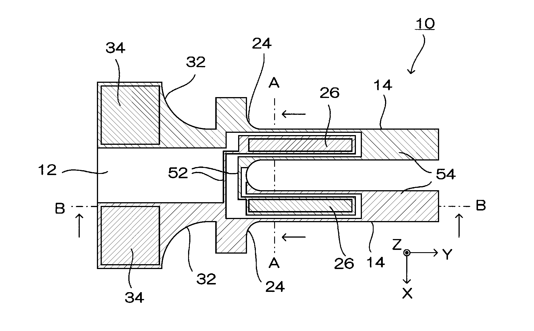
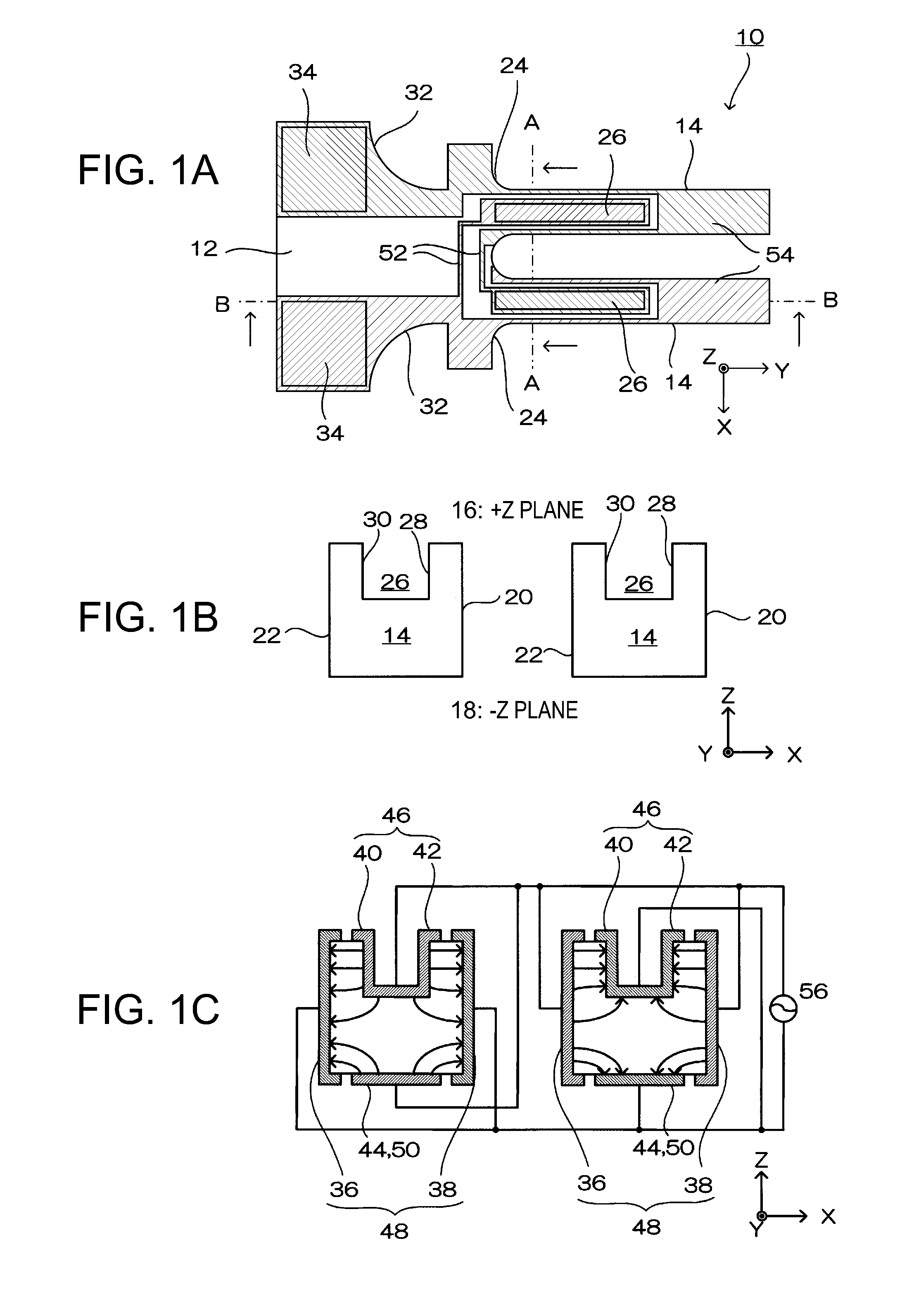
[0048]FIGS. 1A to 1C schematically show a tuning fork type piezoelectric resonator element according to a first embodiment of the invention. FIG. 1A is an overall view, and FIGS. 1B and 1C are sectional views taken along the A-A line of FIG. 1A. Note that later-described embodiments have a whole outer shape that is same as that of the first embodiment, so that the A-A line and the B-B line in FIG. 1A are applied to other embodiments. Further, note that directions of X axis, Y axis, and Z axis that are orthogonal to each other in FIGS. 1A to 1C and a relation between the axes and the tuning fork type piezoelectric resonator element are applied to other embodiments. Furthermore, note that flexural vibration of the tuning fork type piezoelectric resonator element is a fundamental wave mode in each of the embodiments.

[0049]The piezoelectric resonator element according to the first embodiment is composed of a Z-cut piezoelectric plate and includes two resonating arms cantilever-supported...

second embodiment

[0080]FIG. 3A is a schematic view showing a tuning fork type piezoelectric resonator element 10 according to a second embodiment and FIG. 3B is a sectional view showing an A-A line section of the resonator element 10. The tuning fork type piezoelectric resonator element 10 according to the second embodiment basically has the same configuration as that of the first embodiment. However, an adjusting part for adjusting the rigidity with respect to flexural vibration of the resonating arm in the resonator element 10 in the second embodiment is a recess formed on the +Z plane from the base portion side along the free end direction of the resonating arm. Here, the tuning fork type piezoelectric resonator element in the second embodiment and that in embodiments described later have an excitation electrode film, but the structure of the excitation electrode film is same as that in the first embodiment, so that the description thereof will be omitted.

[0081]In the second embodiment, a recess ...

third embodiment

[0083]FIG. 4 is a sectional view showing an A-A line section of a tuning fork type piezoelectric resonator element 10 according to a third embodiment. The tuning fork type piezoelectric resonator element 10 according to the third embodiment has the same basic configuration as the first embodiment. However, an adjusting part for adjusting the rigidity of the resonating arm of the resonator element 10 in the third embodiment includes a first groove and a second groove. The first groove is formed on the +Z plane of the resonating arm from the base portion side along the free end direction, while the second groove is formed on the −Z plane of the resonating arm from the base portion side along the free end direction of the arm. The first groove is formed to be deeper than the second groove. Forming the grooves on the both faces further decreases the CI value of the tuning fork type piezoelectric resonator element 10 compared to the first embodiment. Here, the first groove and the second...


PUM


Abstract

A piezoelectric resonator element includes: a resonating arm extending in a first direction and cantilever-supported; a base portion cantilever-supporting the resonating arm; and an excitation electrode allowing the resonating arm to perform flexural vibration in a second direction that is orthogonal to the first direction. In the piezoelectric resonator element, the resonating arm includes an adjusting part adjusting rigidity with respect to a bend in a third direction that is orthogonal to the first and second directions.

Description

CROSS-REFERENCE TO RELATED APPLICATION[0001]This application is a continuation of U.S. patent application Ser. No. 12 / 256,162, filed on Oct. 22, 2008, which claims priority to Japanese Application No. 2007-285890 filed on Nov. 2, 2007. The entire disclosures of the prior applications are hereby incorporated herein by reference in their entirety.BACKGROUND[0002]1. Technical Field[0003]The present invention relates to a piezoelectric resonator element, a piezoelectric resonator, and an acceleration sensor that reduce sensitivity in other axis.[0004]2. Related Art[0005]In tuning fork type quartz crystal resonators, shapes of front and back faces (XY plane) of a resonating arm are commonly symmetrical. JP-A 2004-200917, for example, discloses a tuning fork type quartz crystal resonator including a resonating arm that has a recessed groove on its front and back faces. Tuning fork type quartz crystal resonators can be used as an acceleration sensor for detecting acceleration in Y-axis dir...

Claims


Application Information

Patent Timeline
Patent Type & Authority Applications(United States)
IPC IPC(8): H01L41/04
CPCH01L41/04H01L41/047H01L41/053H03H9/13H03H9/215H03H9/1021H03H9/19G01P15/0922H10N30/80H10N30/87H10N30/88
Inventor KIKUSHIMA, MASAYUKI
Owner SEIKO EPSON CORP
Why Eureka
Try Eureka