Radio IC device

a radio ic device and antenna technology, applied in the structure of radiating elements, loop antennas, instruments, etc., can solve the problems of large antenna size and unstable communication, and achieve the effect of reducing the overall size of the radio ic device, avoiding deterioration of radiation characteristics, and efficient communication

Inactive Publication Date: 2011-04-21
MURATA MFG CO LTD
View PDF99 Cites 37 Cited by
  • Summary
  • Abstract
  • Description
  • Claims
  • Application Information

AI Technical Summary

Benefits of technology

[0008]To overcome the problems described above, preferred embodiments of the present invention provide a radio IC device that receives and transmits RF signals in a plurality of frequency bands for RFID tags and that is compact and has superior radiation characteristics.

Problems solved by technology

However, an RFID antenna having the structure as shown in Japanese Unexamined Patent Application Publication No. 2005-252853, has a problem in that the antenna size is relatively large because three different antennas must be provided on the same substrate.
Another problem is that, if a plurality of antennas are disposed in close proximity and one of them is used for radio communication, the other antennas interfere with the communication, thus leading to unstable communication.

Method used


Image

  • Radio IC device
  • Radio IC device
  • Radio IC device

Examples


first preferred embodiment

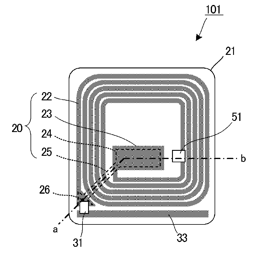
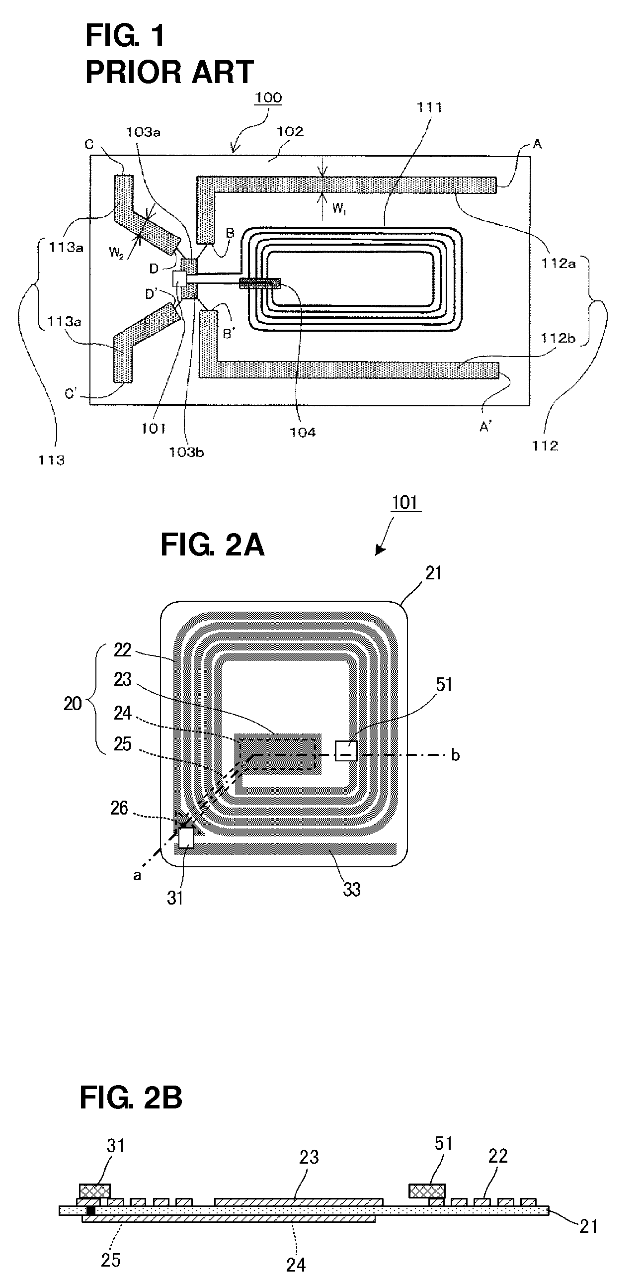
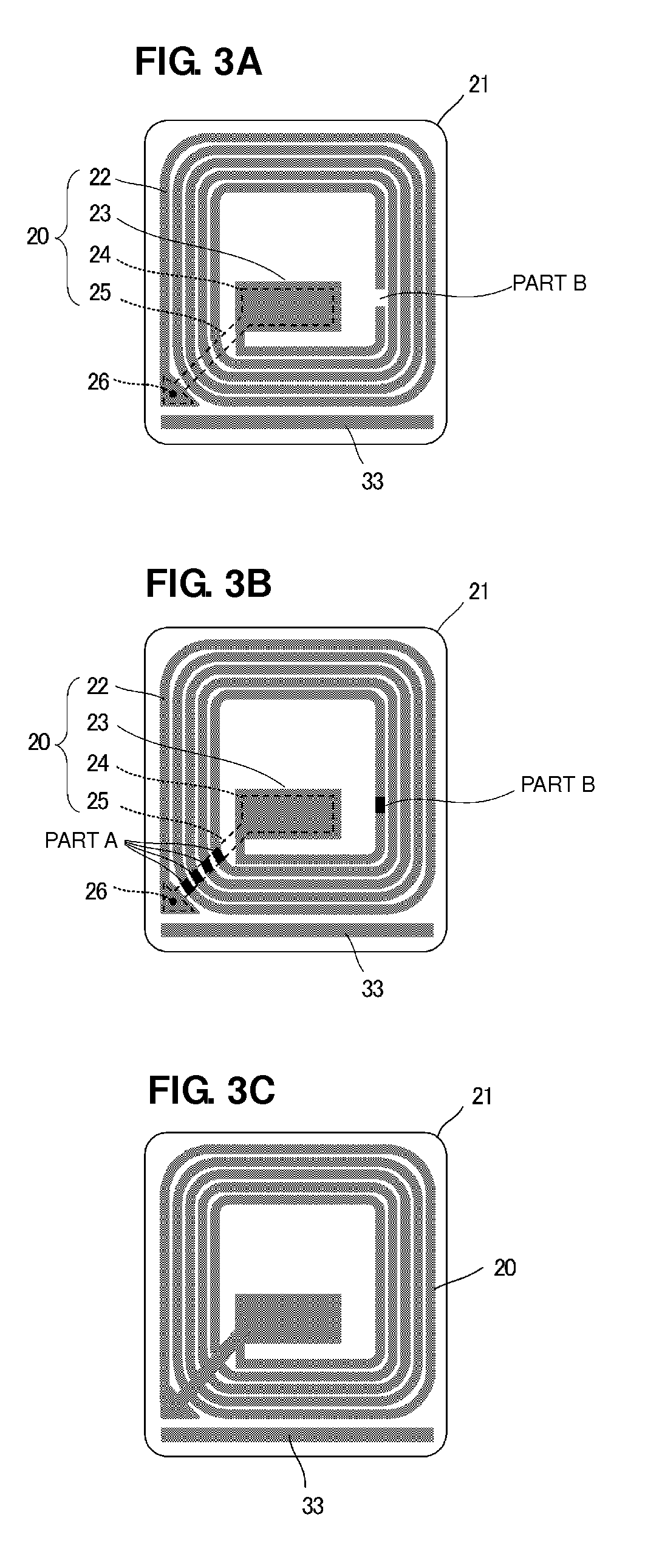
[0062]FIGS. 2A and 2B are diagrams showing the configuration of a radio IC device according to a first preferred embodiment of the present invention. FIG. 2A is a plan view thereof, and FIG. 2B is a sectional view of part a-b in FIG. 2A. In addition, FIGS. 3A to 3C are diagrams showing an electrode pattern on a substrate 21 and the operation thereof. This radio IC device 101 preferably includes various predetermined electrodes provided on the substrate 21 and RFID tag radio ICs 31 and 51, defined by IC chips, mounted on the substrate 21.

[0063]In FIGS. 2A and 2B, the radio IC device 101 preferably includes a desired electrode conductor pattern, such as copper or aluminum, for example, provided on the substrate 21, which is preferably made of a resin film, such as PET or PP, for example. Specifically, a resin sheet including copper or aluminum foil laminated thereto, for example, is preferably used, and the copper or aluminum foil is patterned by etching, for example.

[0064]As shown in...

second preferred embodiment

[0080]FIGS. 4A to 4C are plan views of a radio IC device according to a second preferred embodiment of the present invention. As shown in FIGS. 2A and 2B, the linear electric-field radiation electrode portion 33 is preferably arranged along one side of the spiral line electrode portion 22 and one side of the substrate 21. FIGS. 4A to 4C differ from FIGS. 2A and 2B in the shape of the electric-field radiation electrode portion 33. In a radio IC device 102A in FIG. 4A, an electric-field radiation electrode portion 33a preferably has a folded shape so as to reciprocate along one side of the line electrode portion 22 and one side of the substrate 21, for example.

[0081]In a radio IC device 102B in FIG. 4B, an electric-field radiation electrode portion 33b preferably has a linear or substantially linear shape so as to extend along one side of the substrate 21 in a direction away from the magnetic-field radiation electrode portion 20, for example.

[0082]In a radio IC device 102C in FIG. 4C,...

third preferred embodiment

[0087]FIG. 5 is a plan view of a radio IC device according to a third preferred embodiment of the present invention. FIG. 6 is a sectional view of a first RFID tag electromagnetic coupling module 50 used in the radio IC device 103. FIG. 7 is a sectional view of a second RFID tag electromagnetic coupling module 30 used in the radio IC device 103.

[0088]The first RFID tag electromagnetic coupling module 50 preferably includes a feed circuit board 52 and a radio IC chip 54 mounted thereon. The second RFID tag electromagnetic coupling module 30 preferably includes a feed circuit board 32 and a radio IC chip 34 mounted thereon. While the two connection terminals provided on the radio IC 51 are directly connected to the electrode-removed region of the magnetic-field radiation electrode portion 20 in the first and second preferred embodiments, the first RFID tag electromagnetic coupling module 50 is preferably electromagnetically coupled to the magnetic-field radiation electrode portion 20 ...


PUM


Abstract

A radio IC device that can be used in a plurality of frequency bands for RFID tags and that is compact and has superior radiation characteristics is provided. A spiral line electrode portion and a first side electrode, extending from an inner end thereof, of a capacitor electrode portion are provided on a top surface of a sheet-shaped substrate, and a second side electrode arranged to face the first side electrode and a crossing line electrode are provided on a bottom surface of the substrate. A first radio IC chip is arranged at a location in the line electrode portion, and a second RFID tag radio IC is arranged so as to be connected to a front-to-back connection portion and an end of an electric-field radiation electrode portion. The radio IC chip rectifies an RF signal in a first frequency band and outputs and supplies power to the second RFID tag radio IC.

Description

BACKGROUND OF THE INVENTION[0001]1. Field of the Invention[0002]The present invention relates to radio IC devices, and more particularly, to a radio IC device preferably for use in a radio-frequency identification (RFID) system for noncontact data communication using electromagnetic waves.[0003]2. Description of the Related Art[0004]Recently, RFID systems for transmitting information by noncontact communication between a reader / writer that generates an induction field and an RFID tag attached to an article and storing predetermined information have been used as article management systems.[0005]Japanese Unexamined Patent Application Publication No. 2005-252853 discloses an RFID antenna that transmits and receives frequencies used in RFID, such as 13.56 MHz, 950 MHz, and 2.45 GHz.[0006]FIG. 1 is a diagram showing the configuration of a noncontact IC tag that includes the RFID antenna of Japanese Unexamined Patent Application Publication No. 2005-252853. As shown in FIG. 1, antenna por...

Claims


Application Information

Patent Timeline
Patent Type & Authority Applications(United States)
IPC IPC(8): H04Q5/22G06K19/07G06K19/077H01Q1/38H01Q5/00H01Q5/10H01Q5/35H02J50/00H02J50/05H02J50/12
CPCH01Q5/35G06K19/0701G06K19/0724G06K19/07749G06K19/07756G06K19/07767H01Q9/285G06K19/07783G06K19/07786H01Q1/2225H01Q1/248H01Q7/00G06K19/07779
Inventor IKEMOTO, NOBUO
Owner MURATA MFG CO LTD
Why Eureka
Try Eureka