

Carbon nanotube composite, method for making the same, and electrochemical capacitor using the same
a carbon nanotube and composite technology, applied in the field of composites, can solve the problems of difficult processing of carbon nanotube products in the common powder form, low mechanical strength and toughness and high surface energy of carbon nanotube yarn
- Summary
- Abstract
- Description
- Claims
- Application Information
AI Technical Summary
Problems solved by technology
Method used
Image

Examples
example 1
[0089]Referring to FIG. 9 and FIG. 10, a Pt-carbon nanotube composite film is produced by steps of:
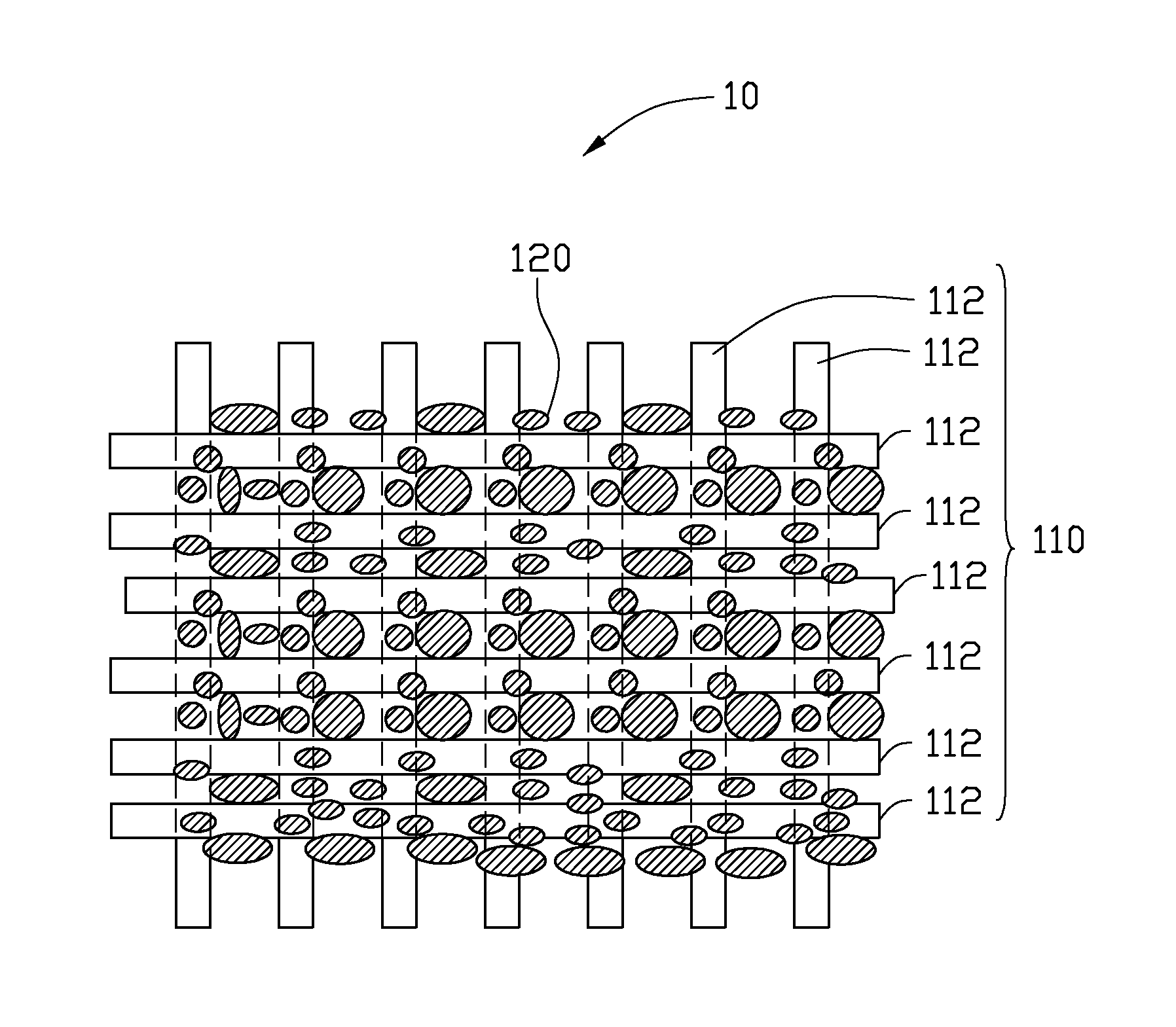
[0090](S101) providing a carbon nanotube structure 110;
[0091](S102) soaking the carbon nanotube structure 110 in a chloroplatinic acid solution; and
[0092](S103) heating the soaked carbon nanotube structure 110 to about 300° C. in nitrogen gas in an oven.
[0093]In this example, the carbon nanotube structure 110 has six stacked carbon nanotube films. Carbon nanotubes in each film are aligned substantially perpendicular to the carbon nanotubes in adjacent films. The carbon nanotube structure 110 covers a metal ring. During soaking of the carbon nanotube structure 110, chloroplatinic acid infiltrates the micropores and / or clearances in the carbon nanotube structure 110. More specifically, the chloroplatinic acid solution is methanol with about 2% by mass of the chloroplatinic acid dissolved in it. In step (S102), the chloroplatinic acid solution can be dropped on the surface of the carbon n...
example 2
[0095]Referring to FIG. 6 and FIG. 7, a Co3O4-carbon nanotube composite film is produced by steps of:
[0096](S201) providing a carbon nanotube structure 110;
[0097](S202) soaking the carbon nanotube structure 110 with a cobalt nitrate solution;
[0098](S203) heating the soaked carbon nanotube structure 110 to about 300° C. in hydrogen gas in an oven.
[0099]In this example, the carbon nanotube structure 110 has twenty stacked carbon nanotube films. The carbon nanotubes of each carbon nanotube film are aligned substantially perpendicular to the carbon nanotubes in adjacent films. The carbon nanotube structure 110 covers a metal ring. By soaking the carbon nanotube structure 110, cobalt nitrate is infiltrated into the micropores and / or clearances of the carbon nanotube structure 110. More specifically, the cobalt nitrate solution is methanol with about 20% by mass of the Co(NO3)2.6H2O dissolved in it. In step (S202), the cobalt nitrate solution can be dropped on the surface of the carbon na...
example 3
[0101]Referring to FIG. 13, FIG. 16 and FIG. 17, a Fe2O3-carbon nanotube composite wire structure is produced by steps of:
[0102](S301) providing a carbon nanotube structure 110;
[0103](S302) soaking the carbon nanotube structure 110 by a ferric nitrate solution;
[0104](S303) heating the soaked carbon nanotube structure 110 to about 300° C. with argon gas in an oven.
[0105]In this example the carbon nanotube structure 110 is a carbon nanotube twisted wire. By soaking the carbon nanotube structure 110, ferric nitrate is infiltrated into the micropores and / or clearances of the carbon nanotube structure 110. More specifically, the ferric nitrate solution is methanol with 20% by mass of the ferric nitrate in it. In step (S302), the carbon nanotube structure 110 can be disposed in the ferric nitrate solution and then taken out therefrom. In step (S303), the ferric nitrate solution soaked carbon nanotube structure 110 is heated to about 300° C. in argon gas, to decompose the ferric nitrate to...
PUM
| Property | Measurement | Unit |
|---|---|---|
| thickness | aaaaa | aaaaa |
| size | aaaaa | aaaaa |
| size | aaaaa | aaaaa |
Abstract
Description
Claims
Application Information