Method of and apparatus for controlling oil temperature increase for electric vehicle and electric vehicle

Inactive Publication Date: 2011-04-28
HONDA MOTOR CO LTD
View PDF2 Cites 45 Cited by
  • Summary
  • Abstract
  • Description
  • Claims
  • Application Information

AI Technical Summary

Benefits of technology

[0015]It is an object of the present invention to provide a method of and an apparatus for controlling an oil temperature increase for an electric vehicle to warm the oil quickly when the temperature of the oil is equal to or lower than a pre

Problems solved by technology

The increase in the resistance to the rotation of the motor tends to reduce the efficiency of the motor, i.e., the efficiency with which to convert electric power into motor power and the efficiency with which to convert electric power into drive power for the wheels.
However, since the upper temperature limit of the coils is governed by the upper temperature limit (about 200° C.) of the wire insulations of the coils, there is a certain limitation to t

Method used


Image

  • Method of and apparatus for controlling oil temperature increase for electric vehicle and electric vehicle
  • Method of and apparatus for controlling oil temperature increase for electric vehicle and electric vehicle
  • Method of and apparatus for controlling oil temperature increase for electric vehicle and electric vehicle

Examples


1st example

[0062]A process of energizing the coils 30 according to a first example will be described below with reference to FIGS. 4, 5, 6, and 7.

[0063]In FIGS. 4 and 5, the position of each permanent magnet 26 on the rotor 28, which is detected by the resolver 36, is held in alignment with the central position between two adjacent slots 112 in the stator 32, i.e., the rotational torque of the rotor 28 is nil (0 N·m). In this position, as shown in FIGS. 4 and 6, the coil 30 wound around a stator core tooth 110 between the slots 112 is energized in first one-half ½·Tpd of a given periodic cycle Tpd (given frequency) by an electric current having a value I1a at an advanced angle of 90°, which is one of the advanced angles for no torque, such that the magnetic flux φm produced by the permanent magnet 26 and the magnetic flux φc produced by the coil 30 are in opposite directions and a combined magnetic flux φs, i.e., a combination of the magnetic flux φm and the magnetic flux φc, is smaller. Then,...

2nd example

[0074]In FIG. 4, when the electric current I1a is supplied to the coil 30 at the advanced angle of 90°, the coil 30 generates the magnetic flux φc in the opposite direction to the magnetic flux φm generated by the permanent magnet 26, i.e., in the direction to demagnetize the permanent magnet 26. According to a second example, as shown in FIGS. 8 and 9, an electric current value I1b is supplied to the coil 30 at the advanced angle of 90° for a period T1 to generate the magnetic flux φc in the opposite direction to the magnetic flux φm generated by the permanent magnet 26, and an electric current value I2b (=I1b) is supplied to the coil 30 at the advanced angle of 270° for a period T2 longer than the period T1 (T1+T2=Tpd) to generate the magnetic flux φc in the same direction as the magnetic flux φm generated by the permanent magnet 26. Since the period T2 is longer than the period T1, the permanent magnet 26 is prevented from being unduly demagnetized, and the stator 32 is heated by...


PUM


Abstract

An electric vehicle employs an oil commonly used as a lubricating oil for gears and a coolant for a motor and is propelled by transmitting the rotational torque of the motor to wheels through the gears, the motor being partly immersed in the oil. It is determined whether the motor is in a state prior to being started or not. If it is judged that the motor is in the state prior to being started, coils of the motor are energized alternately with a first current supplied to the motor at an advanced angle for no torque to generate a magnetic flux, and a second current supplied to the motor at another advanced angle for no torque to generate a magnetic flux in a direction opposite to the magnetic flux generated by the first current, thereby heating the oil.

Description

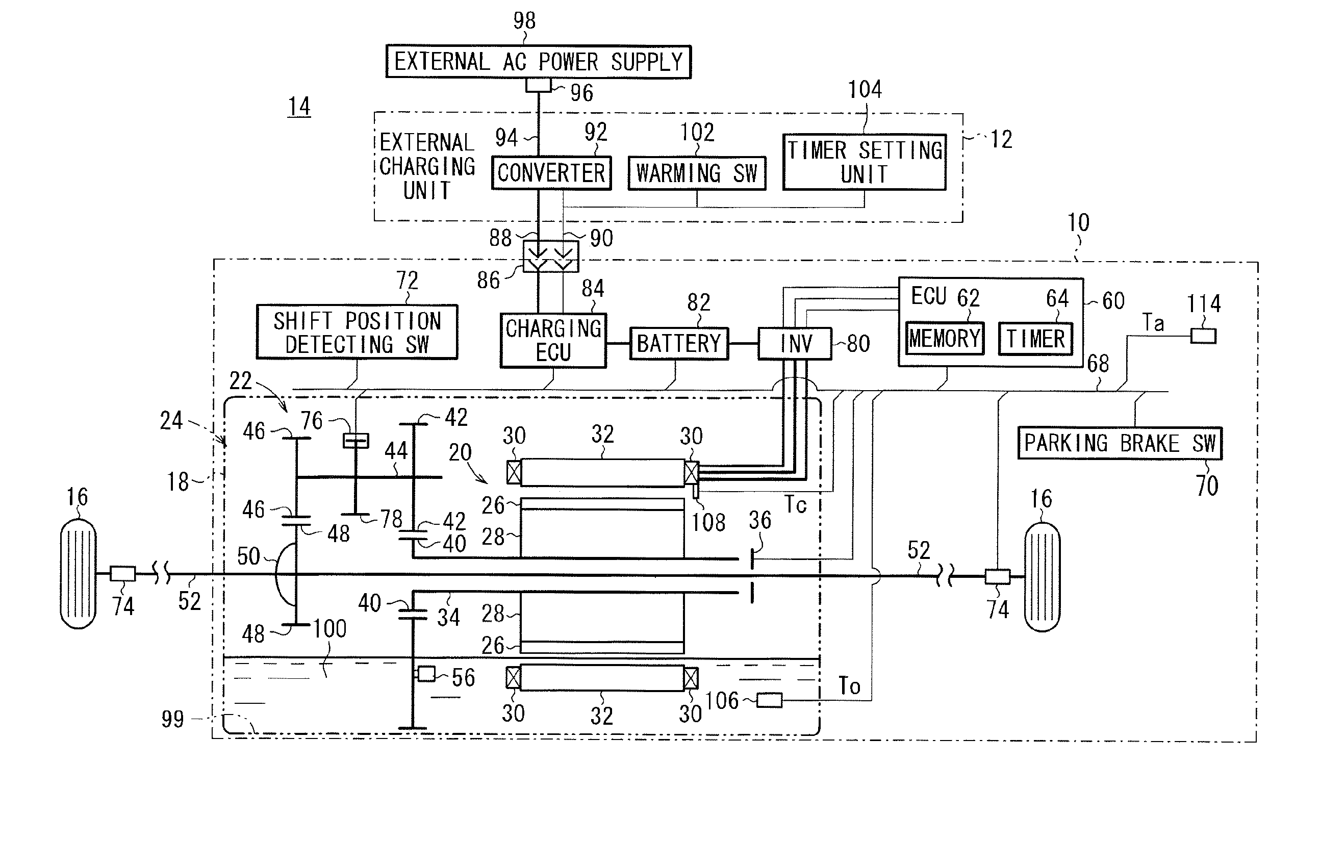
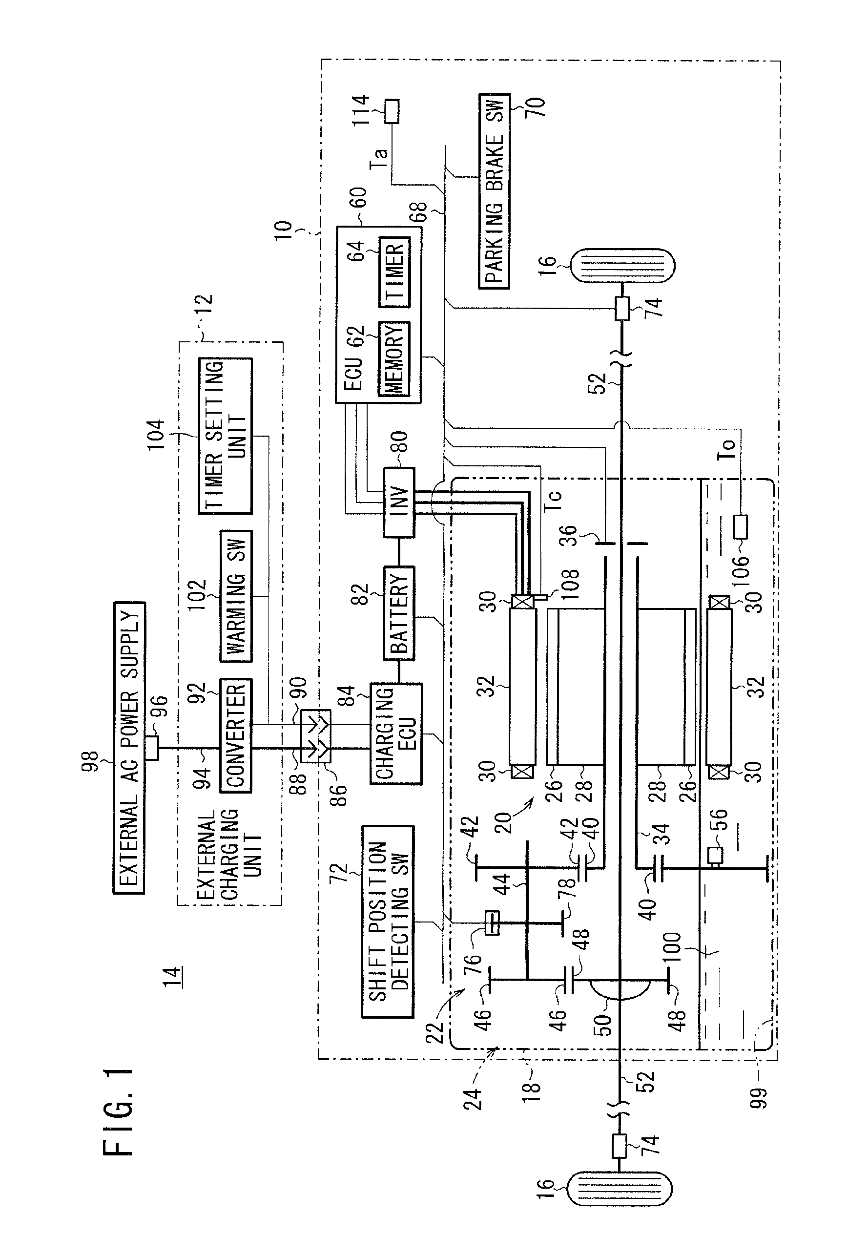
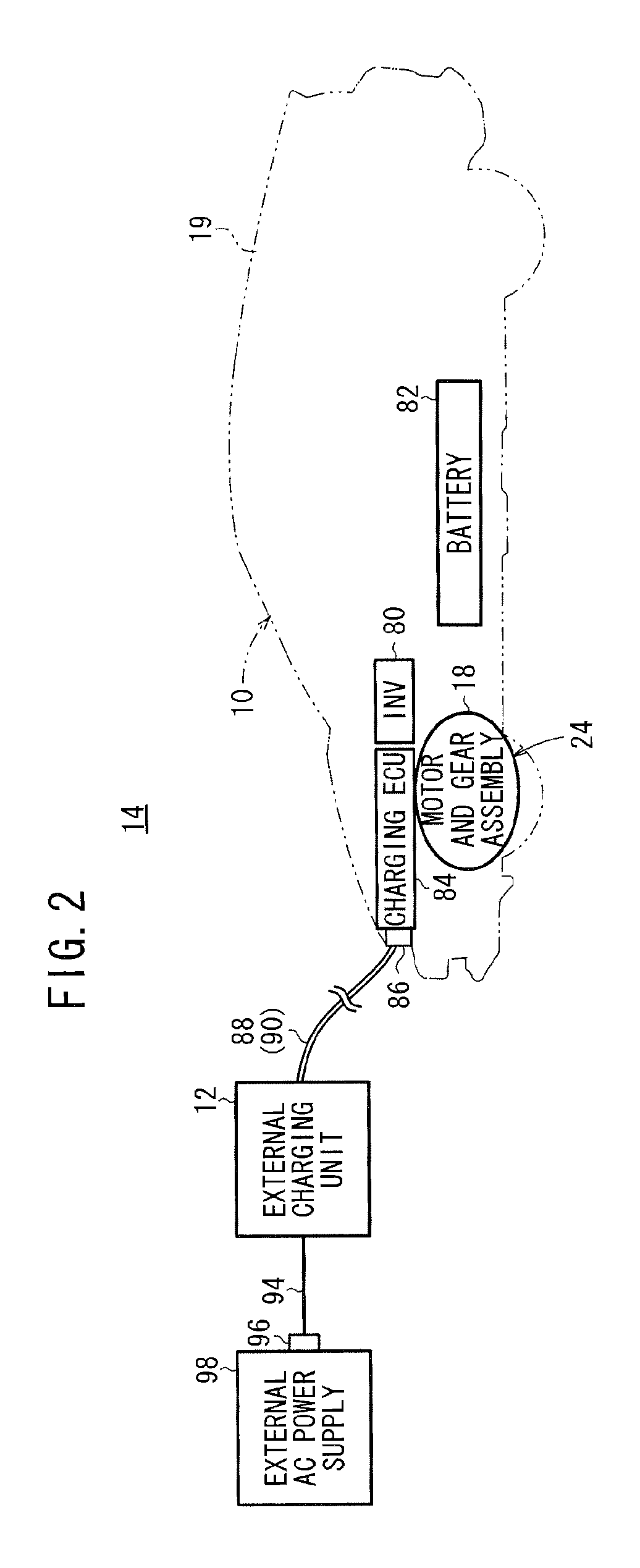
CROSS-REFERENCE TO RELATED APPLICATION[0001]This application is based upon and claims the benefit of priority from Japanese Patent Application No. 2009-245516 filed on Oct. 26, 2009, of which the contents are incorporated herein by reference.BACKGROUND OF THE INVENTION[0002]1. Field of the Invention[0003]The present invention relates to an electric vehicle which is propelled by an electric motor (hereinafter referred to as “motor”) energized by electric power when the rotational torque generated by the motor is transmitted to wheels through gears, and more particularly to a method of and an apparatus for controlling an oil temperature increase for an electric vehicle which employs an oil commonly used as a lubricating oil for the gears and a coolant for the motor, and an electric vehicle incorporating such a method and an apparatus.[0004]2. Description of the Related Art[0005]Heretofore, there have been commercially available electric vehicles which are propelled by a motor energize...

Claims


Application Information

Patent Timeline
IPC IPC(8): H02P7/06
CPCB60L1/06Y02T10/7275B60L11/1803B60L11/1816B60L15/20B60L2230/16B60L2240/36B60L2250/10F16H57/0413F16H57/0476H02P29/005Y02T10/642Y02T10/7005Y02T10/7088Y02T90/128Y02T90/14Y02T90/163B60L3/0061Y02T10/72H02P29/62B60L53/14B60L50/51B60L53/305Y02T10/64Y02T10/7072Y02T90/12Y02T90/16Y02T10/70
Inventor TAKIZAWA, DAIJIRO
Owner HONDA MOTOR CO LTD
Why Eureka
Try Eureka