Method & apparatus for processing fischer-tropsch off-gas

a technology of fischertropsch and off-gas, which is applied in the direction of combustible gas catalytic treatment, sustainable manufacturing/processing, and separation processes, etc., can solve the problems of reducing the flue gas carbon dioxide level, and reducing the effect of carbon dioxide in the flue gas

Inactive Publication Date: 2011-04-28
SHELL OIL CO
View PDF0 Cites 15 Cited by
  • Summary
  • Abstract
  • Description
  • Claims
  • Application Information

AI Technical Summary

Benefits of technology

[0023]An advantage of the process according to the invention is that not only the fraction that is subjected to syngas manufacturing is a carbon dioxide depleted Fischer-Tropsch off-gas but also the fraction that will be combusted. In this way CO2, methane and CO are removed from the Fischer-Tropsch off-gas at high pressure before this Fischer-Tropsch off-

Problems solved by technology

A disadvantage of the prior art processes described is that the part of the Fischer-Tropsch off-gas used for generating energy comprises a large amount of CO2.
Combustion of the CO2 comprising Fischer-Tropsch off-gas in power generation will lead to CO2 emission.
Removal of CO2 from the flue gas i

Method used


Image

  • Method & apparatus for processing fischer-tropsch off-gas

Examples


first embodiment

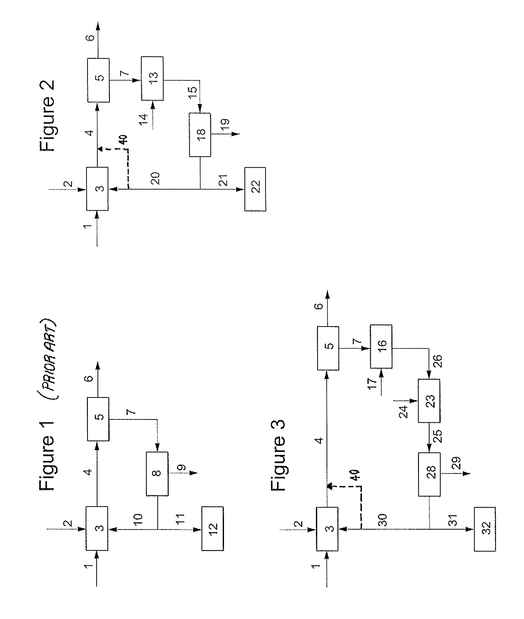
[0052]FIG. 2 illustrates a process according to the invention. The same initial procedure is followed as in FIG. 1, until a separated Fischer-Tropsch off-gas from unit 5 is obtained. Hereafter, the Fischer-Tropsch off-gas is fed trough line 7 to a water gas shift reactor 13. Steam is provided through line 14 to reactor 13, in which the Fischer-Tropsch off-gas is mixed with steam, and the CO present in the Fischer-Tropsch off-gas is reacted to H2 and CO2.

[0053]The CO depleted Fischer-Tropsch off-gas is fed through line 15 to Carbon Capture unit 18, which CO2 is removed from the Fischer-Tropsch off-gas. A CO2 rich stream is separated off through line 19. Suitably, the CO2 is stored or re-used.

[0054]Part of the carbon dioxide depleted Fischer-Tropsch off-gas is recycled through line 20 to the syngas manufacturing unit 3. Optionally, some or all of the carbon dioxide depleted off-gas may be diverted through line 40 and combined directly with the syngas in line 4. Another part of the car...

second embodiment

[0056]FIG. 3 illustrates a process according to the invention. The same initial procedure was followed as in FIG. 1, until a separated Fischer-Tropsch off-gas from unit 5 is obtained. Hereafter, the Fischer-Tropsch off-gas is fed through line 7 to steam methane reformer 16. Steam is provided through line 17 to reformer 16, in which the Fischer-Tropsch off-gas is mixed with steam, and the methane present in the Fischer-Tropsch off-gas is reacted to H2 and CO2. The methane depleted Fischer-Tropsch off-gas is fed through line 26 to a water shift reactor 23. Steam is provided through line 24 to reactor 23, in which the Fischer-Tropsch off-gas is mixed with steam, and the CO present in the Fischer-Tropsch off-gas is reacted to H2 and CO2. The methane and CO depleted Fischer-Tropsch off-gas is fed through line 25 to Carbon Capture unit 28, in which carbon dioxide is removed from the Fischer-Tropsch off-gas. A carbon dioxide rich stream is separated off through line 29. Suitably, the carbo...


PUM

PropertyMeasurementUnit
Energyaaaaaaaaaa

Abstract

This invention concerns methods and apparatus for processing Fischer-Tropsch off-gas comprising the following steps: a) subjecting Fischer-Tropsch off-gas to at least a water gas shift reaction and partial CO2 removal resulting in a Fischer-Tropsch off-gas with significantly reduced levels of carbon dioxide and a CO2 rich stream; and optionally b) subjecting part of the carbon dioxide depleted Fischer-Tropsch off-gas to synthesis gas manufacturing; and c) using another part of the carbon dioxide depleted Fischer-Tropsch off-gas for generating energy.

Description

[0001]This application claims the benefit of European Application No. 09173662.9 filed Oct. 21, 2009, which is incorporated herein by reference.FIELD OF THE INVENTION[0002]The present invention relates to a process for processing Fischer-Tropsch off-gas.BACKGROUND OF THE INVENTION[0003]The Fischer-Tropsch process can be used for the conversion of hydrocarbonaceous feed stocks into normally liquid and / or solid hydrocarbons (i.e. measured at 0° C., 1 bar). The feed stock (e.g. natural gas, associated gas, coal-bed methane, residual oil fractions, biomass and / or coal) is converted in a first step into a mixture of hydrogen and carbon monoxide. This mixture is often referred to as synthesis gas or syngas. The synthesis gas is fed into a reactor where it is converted over a suitable catalyst at elevated temperature and pressure into paraffinic compounds ranging from methane to high molecular weight molecules comprising up to 200 carbon atoms, or, under particular circumstances, even more...

Claims


Application Information

Patent Timeline
IPC IPC(8): C07C1/00B01D53/62
CPCC01B3/34C10J2300/1846C01B3/382C01B2203/0216C01B2203/0233C01B2203/0244C01B2203/025C01B2203/0475C01B2203/062C01B2203/1258C01B2203/142C01B2203/86C10G2/30Y02C10/04C10K1/005C10K3/04C10J2300/1612C10J2300/1659C10J2300/1823C01B3/36Y02C20/40Y02P30/00
Inventor ASSINK, GERRIT JAN BARENDVAN DORST, EVA MARFILIAHENNINGS, ULRICH MARKUS HINRICH
Owner SHELL OIL CO
Why Eureka
Try Eureka