Ultrasound imaging device

a technology of ultrasonic imaging and ultrasonic radiation, which is applied in the field of ultrasonic imaging devices, can solve the problems of unavoidable zsub, zsub>1/sub>, zsub>2/sub>, zsub>4/sub>, etc., and achieve the effect of reducing the degree of image deterioration and enhancing isochronism

Inactive Publication Date: 2011-04-28
HITACHI LTD
View PDF4 Cites 41 Cited by
  • Summary
  • Abstract
  • Description
  • Claims
  • Application Information

AI Technical Summary

Benefits of technology

[0012]The present invention makes it possible to provide enhanced isochronism between signals of beams to be added or synthesized, and reduce the degree of image deterioration due to the aforementioned “blurring.”
[0013]The present invention also makes it possible to control the

Problems solved by technology

The conventional technology has a problem to be solved in that the generation of regions Z0, Z1, Z2, Z3, and Z4, which differ in point spread function synthesis characteristics, is unavoidable no matter what beam steering format is used for scanning.
In addition, even when there is no relative motion, the sound ray path and propagation time of a transmission/reception beam may unexpectedly vary due, for instance, to local variation in sound velocity of living-body.
Further, when multiple transmission/reception beams are to be synthesized, it is necessary to use

Method used


Image

  • Ultrasound imaging device
  • Ultrasound imaging device
  • Ultrasound imaging device

Examples


first embodiment

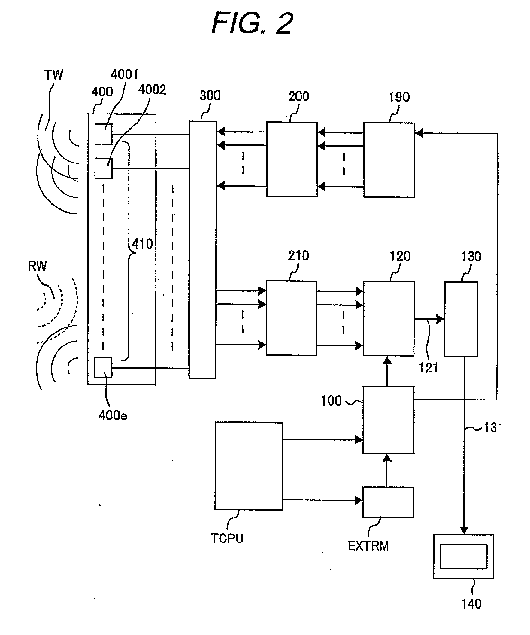
[0025]FIG. 2 shows the configuration of an ultrasound imaging device according to the present invention. A probe 400, which transmits and receives ultrasound waves, incorporates a transmission / reception element group 410 formed by transmission / reception elements 4001, 4002-400e that provide electroacoustic conversion. In most cases, the transmission / reception elements 4001, 4002-400e are made of piezoelectric materials or other ferroelectric materials that generates a pressure from a voltage when transmitting an ultrasound wave and generates a voltage from an ultrasound wave pressure when receiving an ultrasound wave. As is well known, an ultrasound imaging device gives different voltage waveforms to the transmission / reception group 410 to emit a transmission sound wave TW into a living-body, which is a subject, receives a reception sound wave (echo) RW, which is reflected from a specific point of the living-body, compensates for the arrival time difference and phase difference betw...

second embodiment

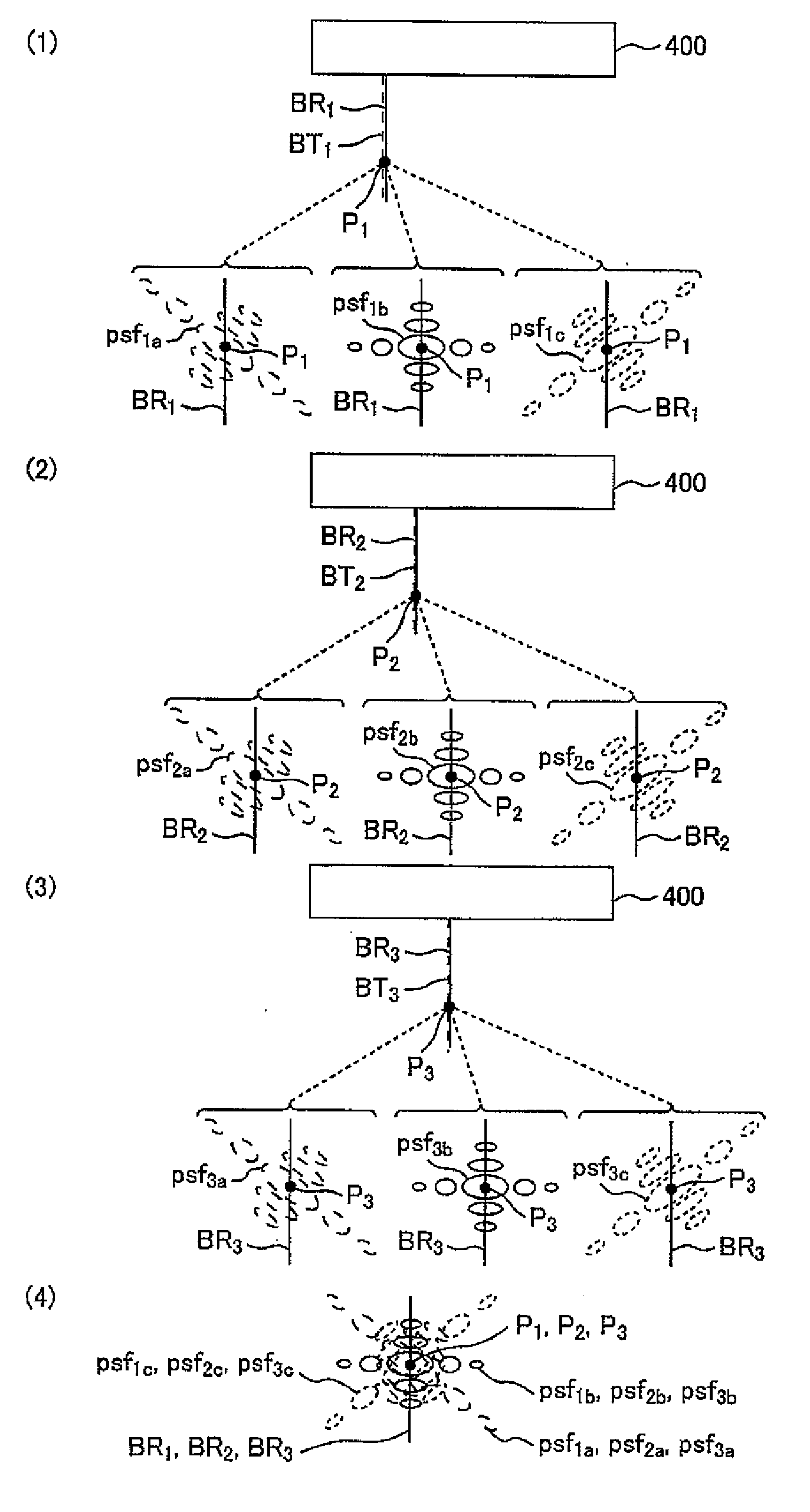
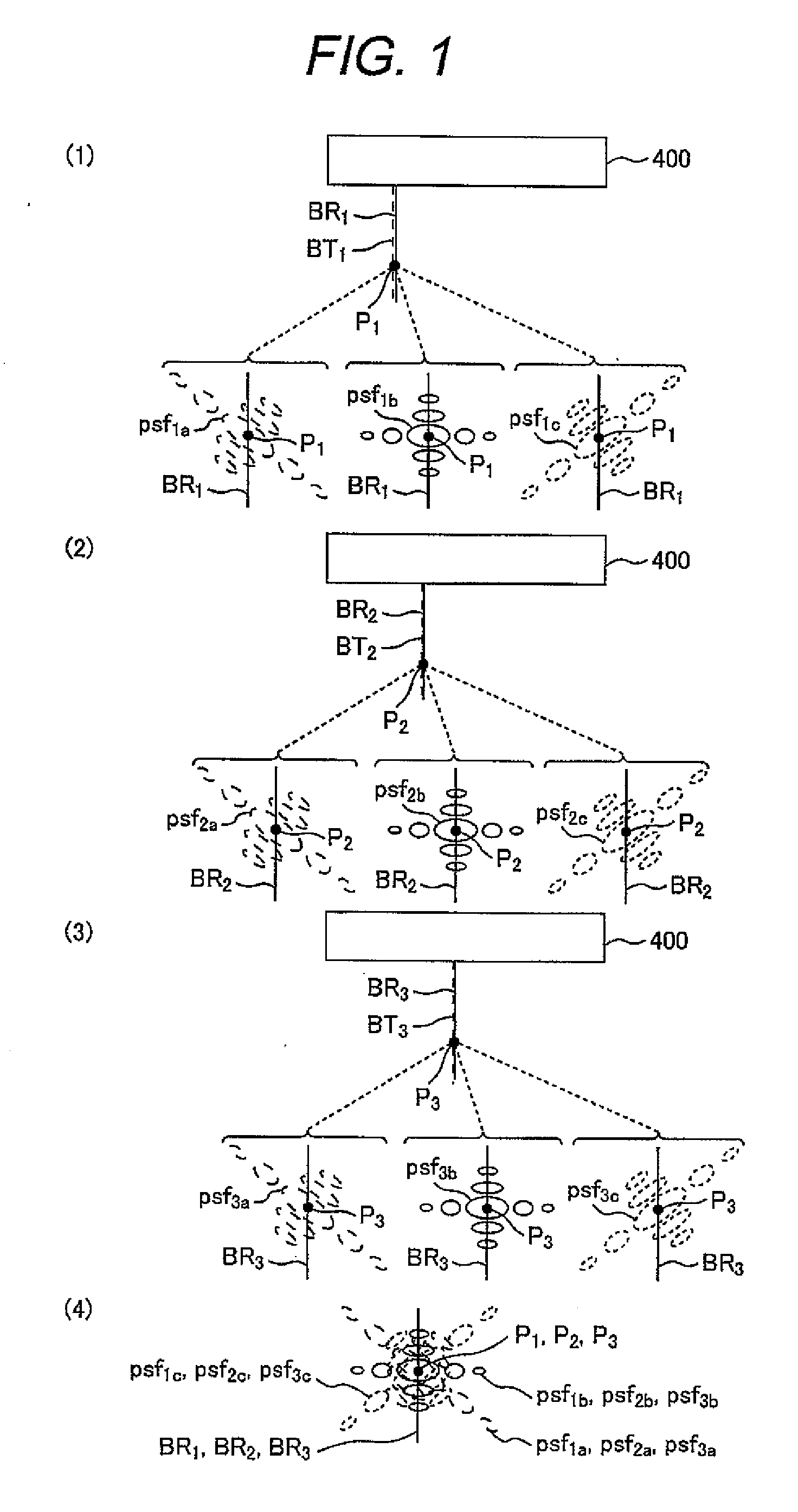
[0040]A typical configuration for enhancing the anisotropic nature of spatial sampling will now be described as a second embodiment. First of all, the principle of anisotropic nature enhancement will be described with reference to FIGS. 10(1) and 10(2). A case where a boundary OBND exists in an imaging region as shown in FIG. 10(1) to cause a strong reflector distribution change that is not orthogonal or parallel to a transmission / reception beam BS will be discussed. When a conventional technology was used, the same point spread function psfb was used at the same depth (at the same distance from the aperture) as point PS no matter whether the anisotropic nature of such reflection exists. Meanwhile, although the boundary OBND is long in a particular direction, the direction of the dominant wave number vector having the best spatial resolution of the point spread function psfb (the direction of the transmission / reception beam BS) is not orthogonal to the direction in which the spatial...


PUM


Abstract

A transmission/reception beamformer output provided with point spread functions having different wave number vector directions is used to obtain a compound image that is highly isochronous and sufficiently blurring-resistant.

Description

BACKGROUND OF THE INVENTION[0001]The present invention relates to an ultrasound imaging device having a beamformer that makes it possible to perform high-definition scanning.[0002]In conventional medical ultrasound imaging systems, there are speckles formed from ensembles of fine scatterers which are smaller than the wave resolution of the systems in principle. In common B-mode imaging in which an attempt is made to recognize in vivo information by locating very small reflection intensity changes, luminance changes in relevant speckle signals are often nearly equivalent to that of reflection intensity changes useful for in vivo diagnosis. It is well-known problem that this equivalence makes it difficult to recognize the in vivo information.[0003]There are several known methods which address the above problem. One method beamforms transmit and receive beam signals at multiple probe aperture positions and / or multiple imaging frequencies, and then adds the signals as coherent signals r...

Claims


Application Information

Patent Timeline
IPC IPC(8): A61B8/14
CPCG01S7/52047G01S7/5209G10K11/341G01S15/8995G01S7/52095
Inventor MASUZAWA, HIROSHI
Owner HITACHI LTD
Why Eureka
Try Eureka