Hydraulic control system monitoring apparatus and method

a monitoring apparatus and control system technology, applied in the direction of fluid pressure measurement by mechanical elements, electric unknown time interval measurement, setting time indication, etc., can solve the problems of prior-art hydraulic bop control systems that may experience delays in subsea bop response time, increased downtime of mux control systems may be significant,

Inactive Publication Date: 2011-04-28
DIAMOND OFFSHORE DRILLING
View PDF16 Cites 36 Cited by
  • Summary
  • Abstract
  • Description
  • Claims
  • Application Information

AI Technical Summary

Benefits of technology

[0013]In one aspect, embodiments disclosed herein relate to a hydraulic control system for operating a subsea blowout preventer, the system including a surface manifold configured to convey hydraulic power to the blowout preventer, a surface actuation valve hydraulically connected to subsea valves and configured to operate the blowout preventer, and a control system monitoring apparatus. The control system monitoring apparatus includes a surface manifold pressure transducer hydraulically connected to the surface manifold, an electronic readback system, and a surface control line pressure transducer hydraulically connected to the surface end of at least one control hose and the surface actuation valve. The control system monitoring apparatus is configured to read, record, and process pressure data supplied by the surface manifold and surface control line pressure transducers.

Problems solved by technology

Studies have shown that MUX electro-hydraulic BOP control systems may have an initial cost about 4 times that of a hydraulic system and over a 5-year period average about 1.8 times more downtime.
Because downtime on a modern floating drilling rig can today cost on the order of $20,000 per hour, the increased downtime of MUX control systems has become a significant issue.
In deep water, however, prior-art hydraulic BOP control systems may experience delays in subsea BOP response time; for this and other reasons, electro-hydraulic control systems, especially MUX systems, may now be typically preferred for drilling in deep water, especially in waters deeper than about 5,000 feet.

Method used


Image

  • Hydraulic control system monitoring apparatus and method
  • Hydraulic control system monitoring apparatus and method
  • Hydraulic control system monitoring apparatus and method

Examples


Embodiment Construction

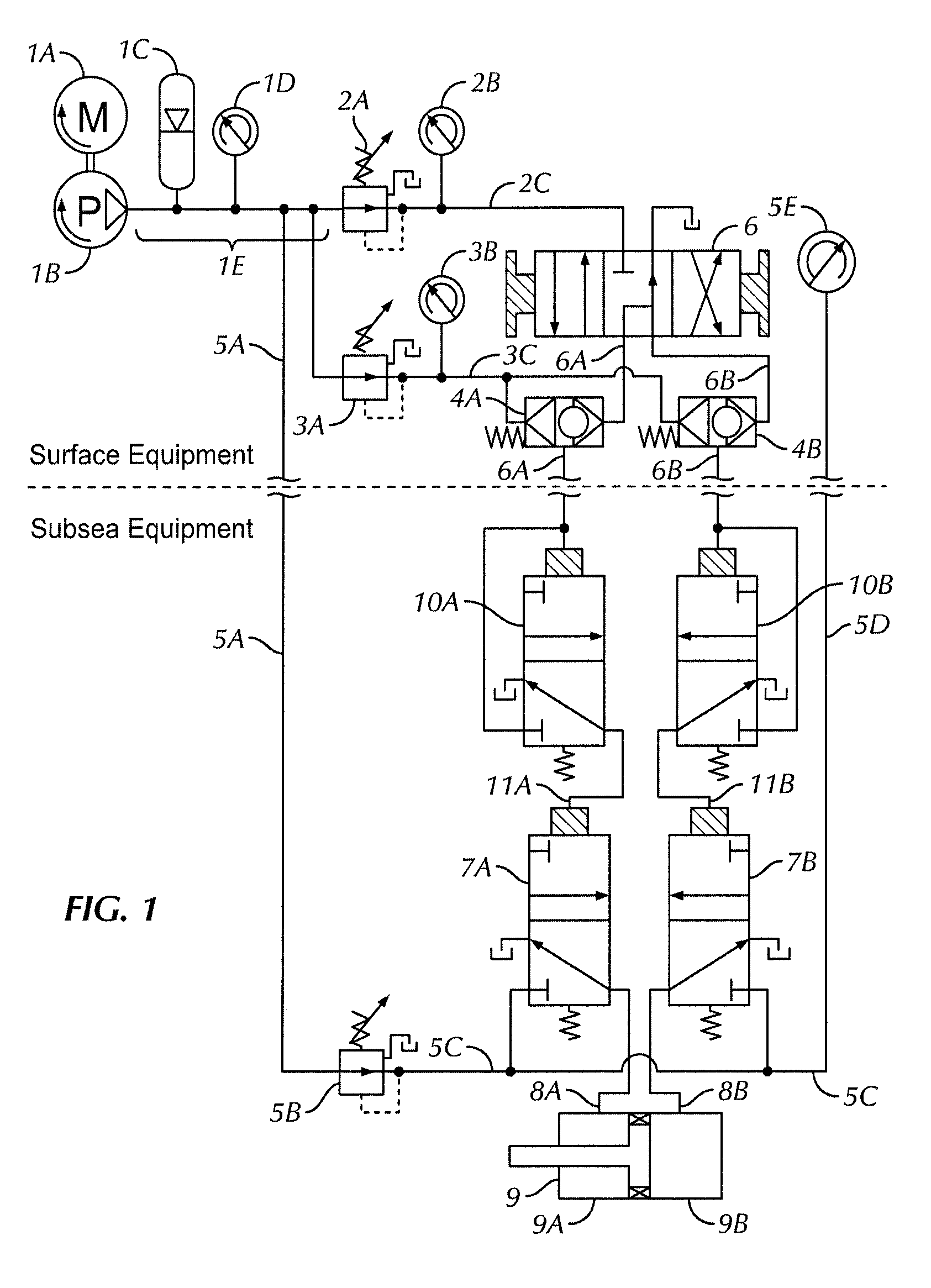
[0019]FIG. 1 is a simplified schematic of one channel of a prior-art hydraulic control system for a subsea BOP stack. Components of the control system may be characterized as either surface equipment or subsea equipment.

[0020]Electric motor 1A drives hydraulic pump 1B, which is hydraulically connected to surface manifold 1E. Hydraulic pressure in surface manifold 1E is maintained by surface manifold accumulator 1C and measured by surface manifold pressure gauge 1D. Surface manifold 1E is also hydraulically connected to subsea hydraulic supply line 5A, which typically includes a series of interconnected steel pipes with inner diameters of 1 inch or more, attached to a drilling riser, to convey hydraulic power from the surface to the subsea BOP proximate the seabed. Surface manifold 1E may typically have a nominal regulated pressure of about 3000 psi, although other nominal regulated pressures may be possible.

[0021]Adjustable pressure regulator 2A sets the pressure in control manifold...


PUM

PropertyMeasurementUnit
closing timeaaaaaaaaaa
lag timeaaaaaaaaaa
timeaaaaaaaaaa

Abstract

A hydraulic control system for operating a subsea blowout preventer includes a surface manifold configured to convey hydraulic power to the blowout preventer, a surface actuation valve hydraulically connected to subsea valves and configured to operate the blowout preventer, and a control system monitoring apparatus. The control system monitoring apparatus includes a surface manifold pressure transducer hydraulically connected to the surface manifold, an electronic readback system, and a surface control line pressure transducer hydraulically connected to the surface end of at least one control hose and the surface actuation valve. The control system monitoring apparatus is configured to read, record, and process pressure data supplied by the surface manifold and surface control line pressure transducers.

Description

CROSS-REFERENCE TO RELATED APPLICATIONS[0001]This application claims priority, under 35 U.S.C. §119(e), to U.S. Patent Application No. 61 / 255,745, filed on Oct. 28, 2009, which is assigned to the present assignee and herein incorporated by reference in its entirety.BACKGROUND[0002]1. Field of the Disclosure[0003]Embodiments disclosed herein relate generally to an improved hydraulic control system for actuation of subsea equipment. More specifically, embodiments disclosed herein relate to apparatus and methods for monitoring the actuation of deepwater subsea blowout preventers (“BOPs”) with a hydraulic control system.[0004]2. Background Art[0005]Deep water drilling for oil and natural gas is conventionally conducted through a subsea blowout preventer (“BOP”) stack, which may be removably attached to a wellhead proximate the seabed. One or more subsea BOPs in the stack may be closed to shut-in the wellbore if, for example, pressurized fluids enter the wellbore from a geological format...

Claims


Application Information

Patent Timeline
Patent Type & Authority Applications(United States)
IPC IPC(8): G06F19/00G01L7/00G04F10/00
CPCE21B47/0001E21B34/16E21B33/064E21B34/04E21B47/001
Inventor CURTISS, III, JASON POST
Owner DIAMOND OFFSHORE DRILLING
Why Eureka
Try Eureka