Method and equipment for producing synthesis gas

a technology of synthesis gas and equipment, applied in the direction of combustible gas production, waste based fuel, products, etc., can solve the problems of complex components (aromatics) and different weight of components, and achieve the effect of reducing the cost of gasification

Active Publication Date: 2011-05-05
CORTUS AB
View PDF8 Cites 5 Cited by
  • Summary
  • Abstract
  • Description
  • Claims
  • Application Information

AI Technical Summary

Problems solved by technology

The problem with gasification of coal, coal by-products, petroleum residues, wastes and biomass is that they are not homogeneous material but components (tar) of different weight and complex components (aromatics) are released during the reaction.
Hence, the ha

Method used


Image

  • Method and equipment for producing synthesis gas
  • Method and equipment for producing synthesis gas

Examples


Embodiment Construction

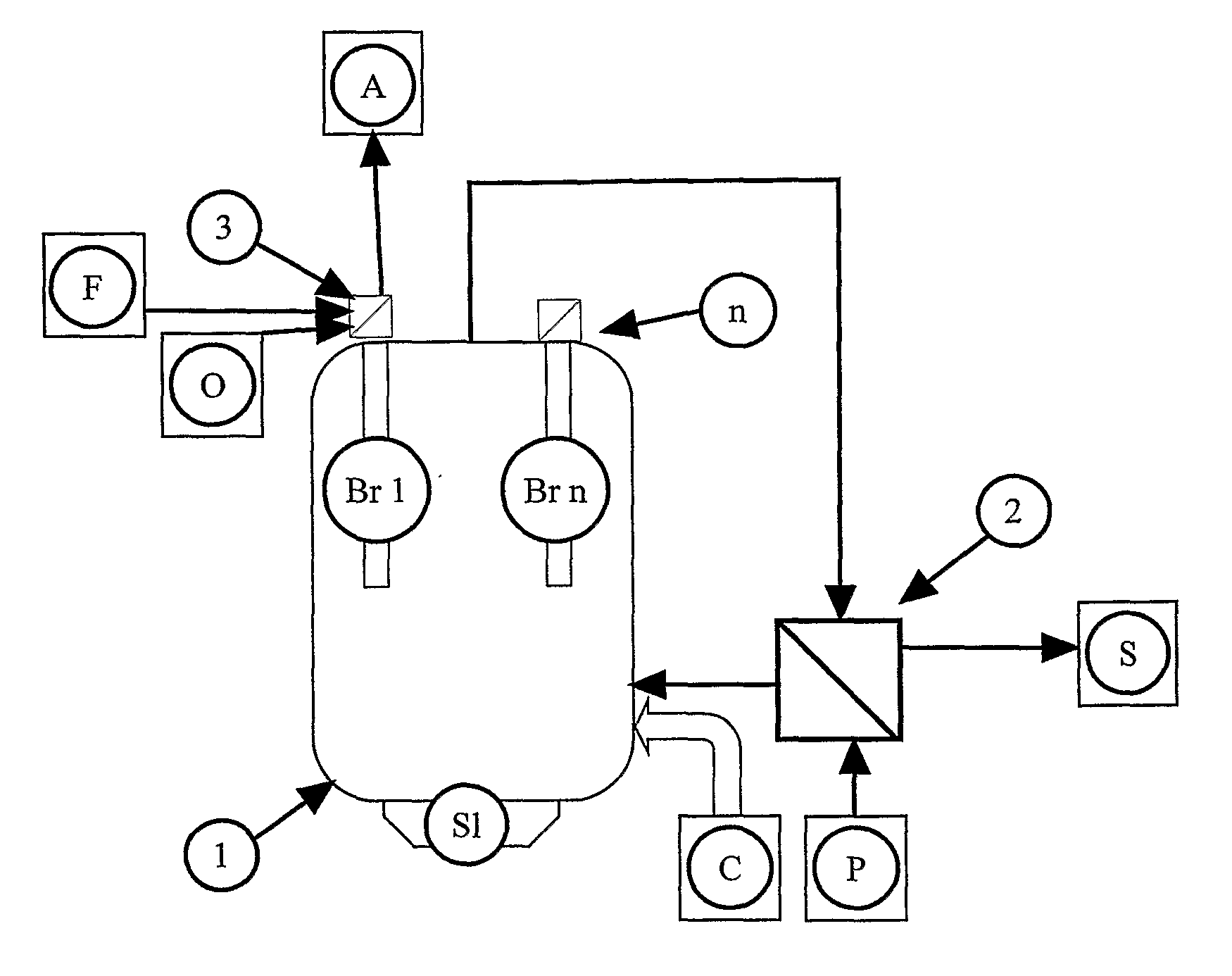
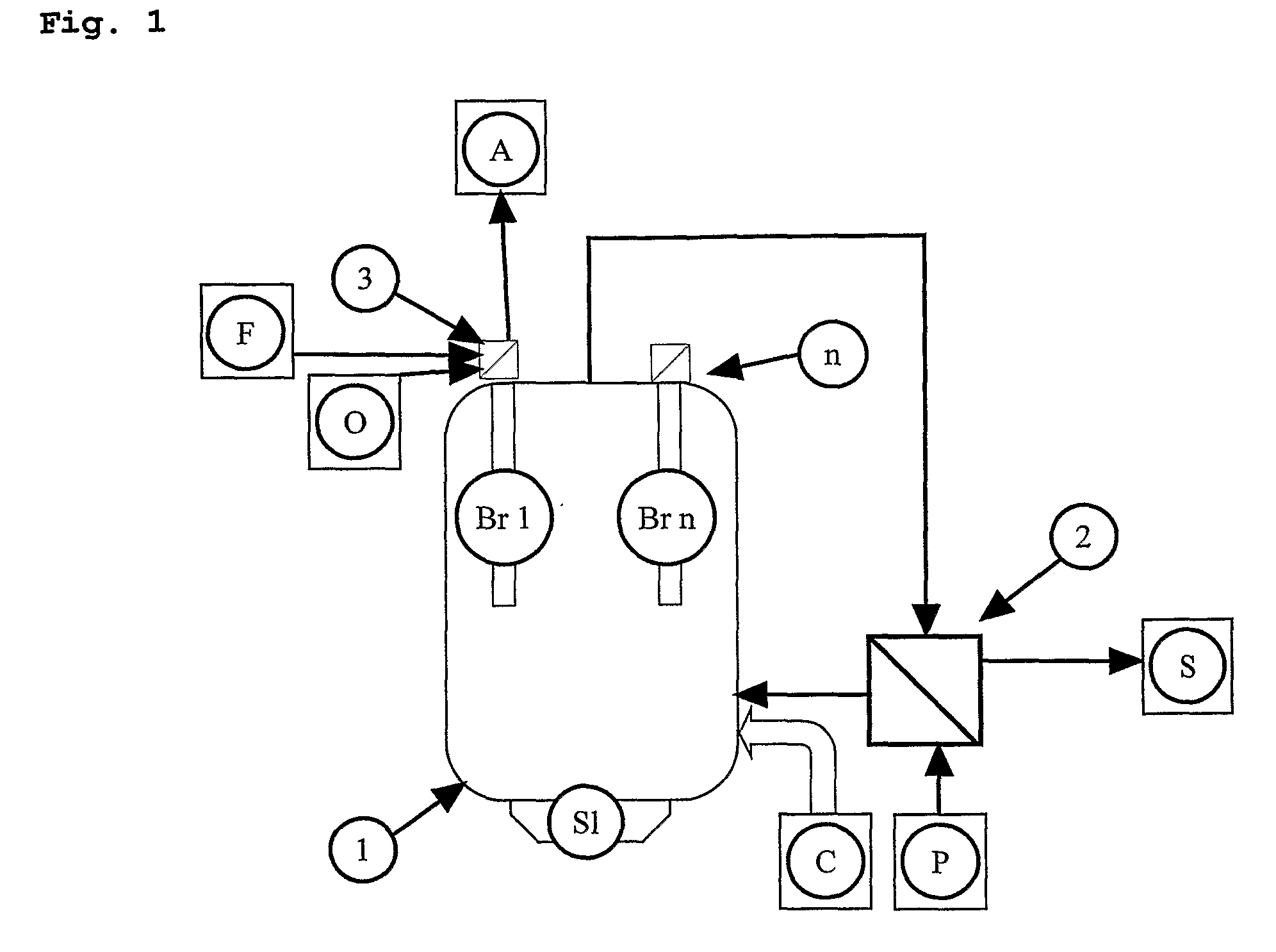
[0012]FIG. 1 shows schematically a number of units making up the equipment to carry out the method. The conduits, pipes, etc., which interconnect the units of the equipment are not described or shown in detail. The conduits, pipes, etc., are appropriately designed to fulfil their function, i.e., to transport gases and solids between units of the equipment.

[0013]FIG. 1 shows an indirectly heated gasification reactor 1 which is normally a ceramic-lined reactor. Solid carbon particles C are fed to the reactor along with the process gas P. The carbon particles C come from a pyrolysis preceding the gasification. The size of the carbon particles C is preferably sufficient to be borne along by incoming gas flow with process gas P into the reactor. The process gas P can be steam or recycled and purified exhaust A from the combustion stage. If the process gas P is recycled exhaust A, it may contain both water steam (H2O) and carbon dioxide (CO2). The process gas P is warmed by heat recovered...


PUM


Abstract

A method and equipment for producing synthesis gas (S) from solid carbon particles (C), the carbon particles (C) being obtained by pyrolysis, gasification of the carbon particles (C) occurs by indirect heating of the carbon particles (C) in the presence of a process gas (P) in the same space where the carbon particles (C) are present, and the synthesis gas (S) generated during the gasification is discharged from the space. The method is characterised in that the carbon particles (C) and the process gas (P) are located in a reactor (1), and the indirect heating occurs by way of radiant heat from burners (Br1-Brn) located in the reactor (1).

Description

TECHNICAL FIELD OF THE INVENTION[0001]The present invention pertains to a method and an equipment for producing synthesis gas from solid carbon particles, said carbon particles being obtained by pyrolysis, gasification of the carbon particles occurs by indirect heating of the carbon particles in presence of a process gas in the same space where the carbon particles are present, and the synthesis gas generated during the gasification is discharged from said space.PRIOR ART[0002]Gasification is a process for producing gaseous fuel from solid fuel. The technique is used for coal, coal by-products, petroleum residues, wastes and biomass. The reactions are based on oxidising gases such as CO2 and H2O) being heated and reacting with carbon ([C] a reducing agent) whereupon carbon monoxide (CO) and hydrogen (H2) are formed, heat being consumed to drive the reactions, which are endothermal. The mixture of carbon monoxide (CO) and hydrogen (H2) is commonly called synthesis gas.[0003]A customa...

Claims


Application Information

Patent Timeline
IPC IPC(8): C10J3/68C10J1/207
CPCC10J3/10C10J3/20C10J2300/0916C10J2300/093C10J2300/0946C10J2300/0973C10J2300/094C10J2300/1246C10J2300/1261C10J2300/1269C10J2300/1861C10J2300/1884C10J3/58C10J2300/1223C10J3/80C10J3/86C10J2300/0913Y02E50/30Y02P20/145C01B3/02
Inventor LJUNGGREN, ROLF
Owner CORTUS AB
Why Eureka
Try Eureka