Fuel injector

Inactive Publication Date: 2011-05-05
VETROVEC JAN
View PDF2 Cites 15 Cited by
  • Summary
  • Abstract
  • Description
  • Claims
  • Application Information

AI Technical Summary

Benefits of technology

[0022]It is still further object of the invention to reduce emissions from internal combustion engines.
[00

Problems solved by technology

In a still another embodiment, the strength of the optical radiation may be made sufficient to ev

Method used


Image

  • Fuel injector
  • Fuel injector
  • Fuel injector

Examples


Example

[0031]Selected embodiments of the present invention will now be explained with reference to drawings. In the drawings, identical components are provided with identical reference symbols in one or more of the figures. It will be apparent to those skilled in the art from this disclosure that the following descriptions of the embodiments of the present invention are merely exemplary in nature and are in no way intended to limit the invention, its application, or uses.

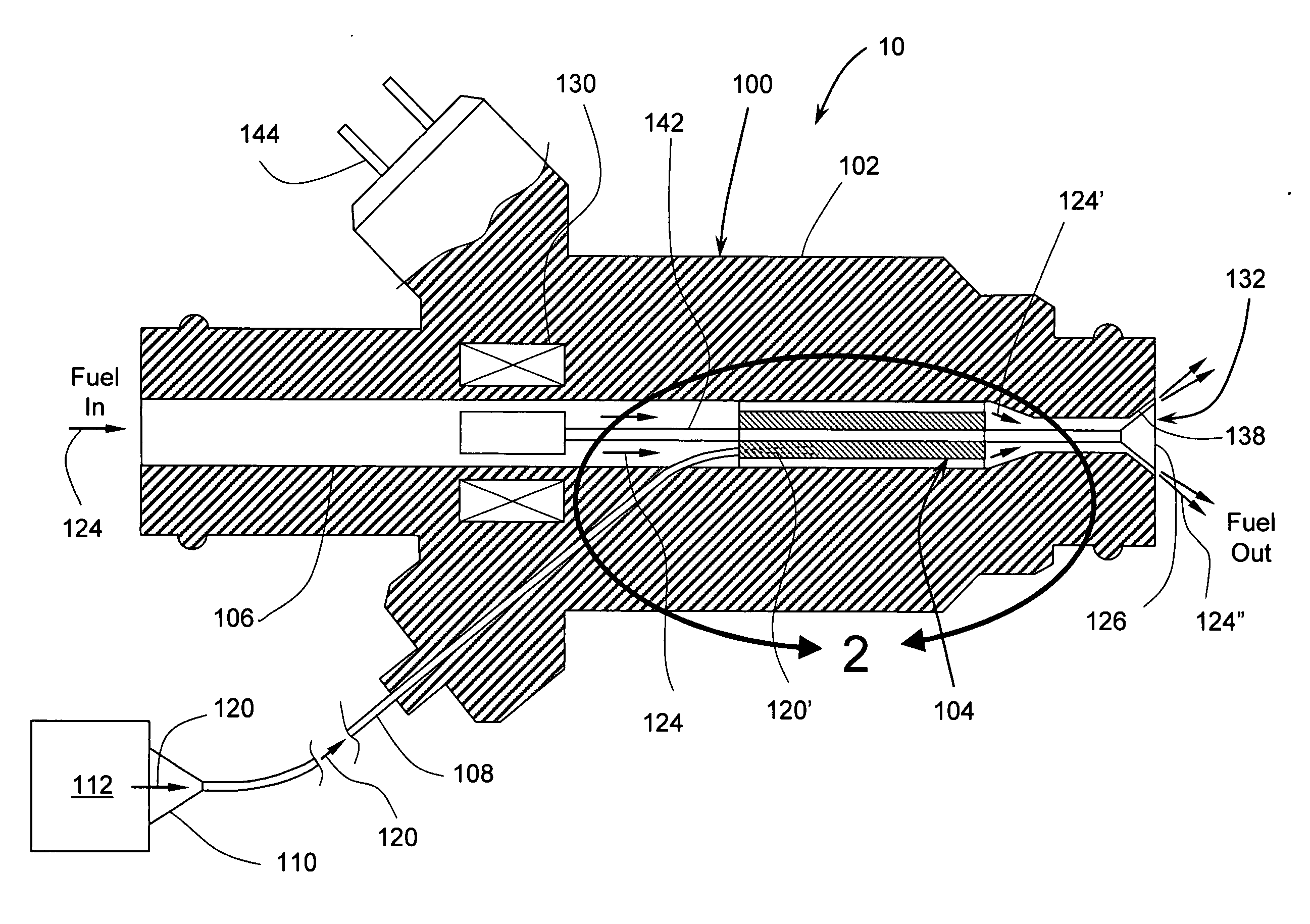
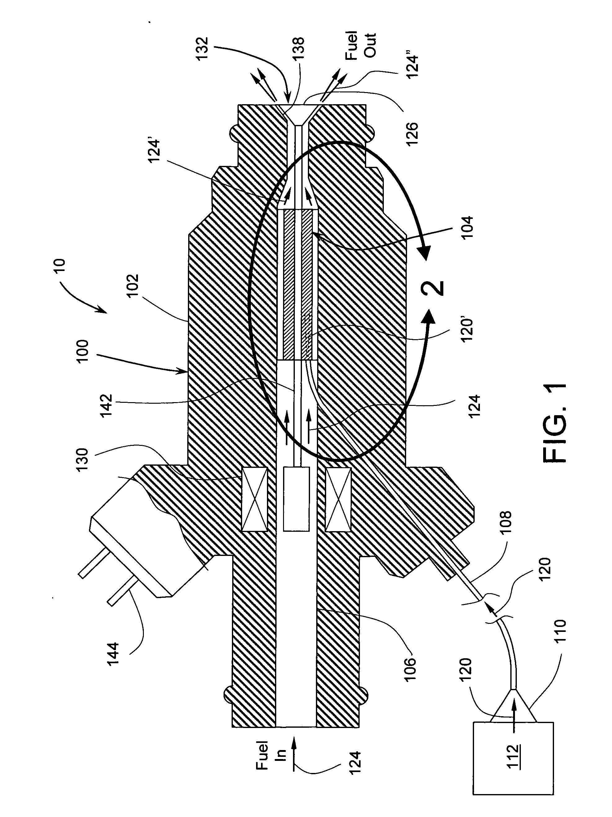
[0032]Referring now to FIG. 1, there is shown a fuel injector system 10 in accordance with one embodiment of the subject invention. The fuel injector system 10 may a fuel injector assembly 100, light source 112, and optical fiber 108. The fuel injector assembly 100 may further comprise an injector body 102, valve 132, actuator 130, valve 132, light absorber / heater 104. The injector body 102 may further include a fuel flow channel 106 and an electrical control connector 144. The fuel flow channel 106 is arranged to receive ...


PUM


Abstract

The invention is for an apparatus and method for a fuel injector enabling improved combustion in automotive engines. In one embodiment of the invention, fuel is preheated for greatly improved atomization and evaporation, especially during cold engine start. As a result, harmful pollution is greatly reduced pollution. In addition, alcohol-based automotive fuel may be used in cold ambient conditions. The invention overcomes the limitations of current electrically heated injectors and fuel rails having large thermal inertia and long preheat times. In another embodiment of the invention, optically-driven acoustic waves assist in atomization of injected fuel, thus resulting in reduced engine emissions and improved efficiency. Other applications include production of finely atomized fluid sprays for the manufacture of substrates for industry, applications of coatings, formation of uniform-sized particles for the production of pharmaceutical products, and thin-film deposition techniques for forming resistors, capacitors and other components.

Description

CROSS-REFERENCE TO RELATED APPLICATIONS[0001]This application claims priority from U.S. provisional patent application U.S. Ser. No. 61 / 268,945, filed on Jun. 18, 2009 and entitled “Heated Fuel Injector.”FIELD OF THE INVENTION[0002]This invention relates generally to heating of fluids by heat generated by optical radiation and more specifically to heating of fuels for internal combustion engines.BACKGROUND OF THE INVENTION[0003]The subject invention is an apparatus and method for heating of fluids by heat generated by absorption of optical radiation and more specifically to heating of fuels prior to injection into internal combustion engines.[0004]Today's standards for low and ultra-low emissions vehicles require increased research and development in unburned hydrocarbon emissions, particularly in operations such as engine cold starts. Some studies show that about 90% of nitrous oxides (NOX) and hydrocarbon (HC) emissions from automotive engines is produced during cold starts. In th...

Claims


Application Information

Patent Timeline
IPC IPC(8): F02M53/04
CPCF02M53/06
Inventor VETROVEC, JAN
Owner VETROVEC JAN
Why Eureka
Try Eureka