Interconnect structure having a via with a via gouging feature and dielectric liner sidewalls for BEOL integration

a technology of dielectric liner sidewalls and interconnect structures, which is applied in the field ofsemiconductor interconnect structures, can solve the problems of reducing the quality of diffusion barriers, increasing problems, and reducing the thermal cycling and stress migration resistance of interconnect structures, so as to improve wiring reliability

Inactive Publication Date: 2011-05-05
ALSEPHINA INNOVATIONS INC
View PDF8 Cites 44 Cited by
  • Summary
  • Abstract
  • Description
  • Claims
  • Application Information

AI Technical Summary

Benefits of technology

[0009]The present invention provides a semiconductor interconnect structure in which at least one via has a via gouging feature and dielectric liner sidewalls. The present invention also provides a method of forming such an interconnect structure. The interconnect structure of the present invention provides improved wiring reliability as compared to conventional interconnect structures mentioned above.

Problems solved by technology

The major problem encountered in this area today is poor mechanical strength of deep submicron metal contacts (lines and vias) embedded in low k dielectric materials, which can cause unsatisfied thermal cycling and stress migration resistance in the interconnect structures.
This problem becomes more severe when new metallization approaches or porous low k dielectric materials are used.
Both of these characteristics reduce the quality of the diffusion barrier 116 and degrade the overall wiring reliability.

Method used


Image

  • Interconnect structure having a via with a via gouging feature and dielectric liner sidewalls for BEOL integration
  • Interconnect structure having a via with a via gouging feature and dielectric liner sidewalls for BEOL integration
  • Interconnect structure having a via with a via gouging feature and dielectric liner sidewalls for BEOL integration

Examples


Embodiment Construction

[0016]The present invention will now be described more fully hereinafter with reference to the accompanying drawings in which preferred embodiments of the invention are shown. This invention may, however, be embodied in many different forms and should not be construed as limited to the illustrated embodiments set forth herein. Rather, these embodiments are provided so that this disclosure will be thorough and complete, and will fully convey the scope of the invention to those skilled in the art. Like numerals refer to like features throughout.

[0017]It will be understood that when an element, such as a layer, is referred to as being “on” or “over” another element, it can be directly on the other element or intervening elements may also be present. In contrast, when an element is referred to as being “directly on” or “directly over” another element, there are no intervening elements present.

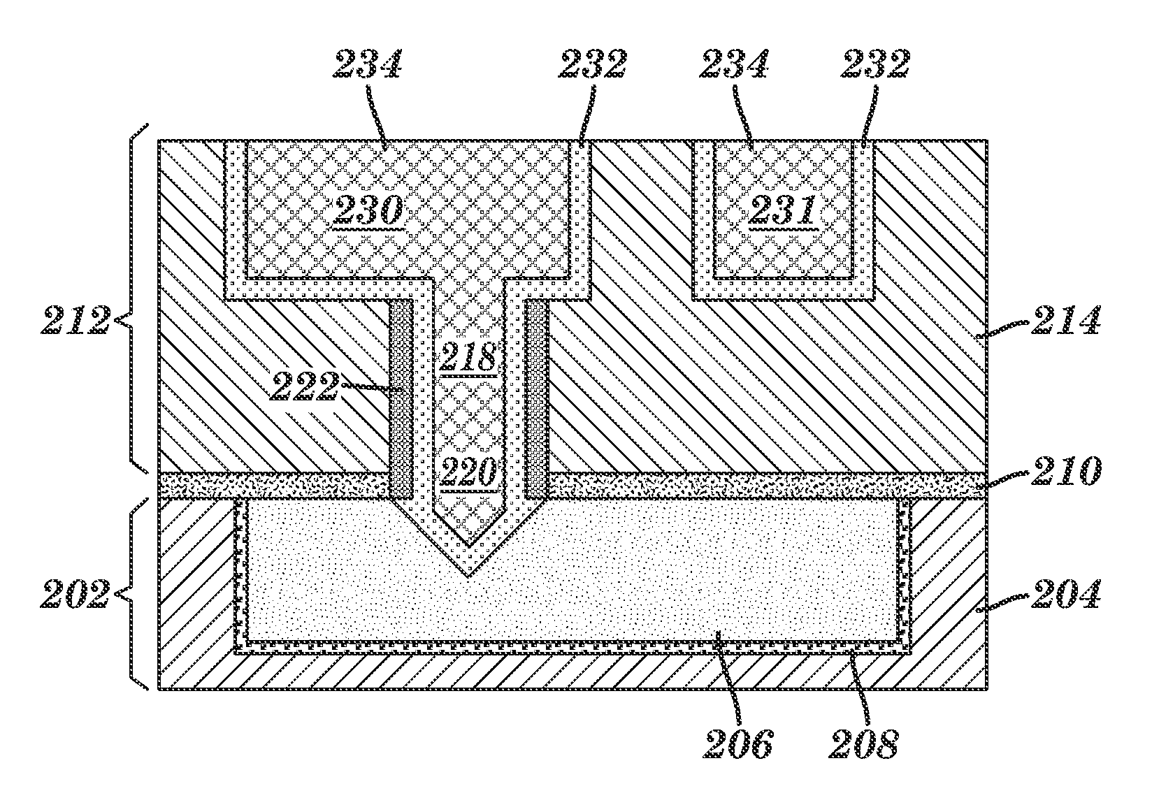
[0018]The present invention provides an interconnect structure in which at least one via has a ...


PUM

PropertyMeasurementUnit
thicknessaaaaaaaaaa
thicknessaaaaaaaaaa
dielectric constantaaaaaaaaaa

Abstract

An interconnect structure including a lower interconnect level with a first dielectric layer having a first conductive material embedded therein; a dielectric capping layer located on the first dielectric layer and some portions of the first conductive material; an upper interconnect level including a second dielectric layer having at least one via opening filled with a second conductive material and at least one overlying line opening filled with the second conductive material disposed therein, wherein the at least one via opening is in contact with the first conductive material in the lower interconnect level by a via gouging feature; a dielectric liner on sidewalls of the at least one via opening; and a first diffusion barrier layer on sidewalls and a bottom of both the at least one via opening and the at least one overlying line opening. A method of forming the interconnect structure is also provided.

Description

FIELD OF THE INVENTION[0001]The present invention relates to a semiconductor interconnect structure, and a method of fabricating the same. More particularly, the present invention relates to a semiconductor interconnect structure in which at least one via has a via gouging feature and dielectric liner sidewalls. The present invention also provides a method of forming such an interconnect structure.BACKGROUND OF THE INVENTION[0002]Manufacture of a semiconductor device is normally divided into two major phases. The “front end of the line” (FEOL) is dedicated to the creation of all the transistors in the body of the semiconductor device, and the “back end of the line” (BEOL) creates the metal interconnect structures, which connect all the transistors with each other as well as with the external world. The FEOL consists of a repeated sequence of steps that modifies the electrical properties of part of a wafer surface and grows new material above selected regions. Once all active compone...

Claims


Application Information

Patent Timeline
Patent Type & Authority Applications(United States)
IPC IPC(8): H05K1/11H01R43/16
CPCH01L21/76805H01L21/76808Y10T29/49204H01L21/76835H01L2221/1036H01L21/76831
Inventor YANG, CHIH-CHAOHU, CHAO-KUN
Owner ALSEPHINA INNOVATIONS INC
Why Eureka
Try Eureka