Clutchless wire cutting apparatus

Inactive Publication Date: 2002-09-19
ROCKFORD MFG GROUP
View PDF1 Cites 8 Cited by
  • Summary
  • Abstract
  • Description
  • Claims
  • Application Information

AI Technical Summary

Benefits of technology

0007] It is the main objective of the present invention to increase the reliabilit

Problems solved by technology

While the clutch/brake mechanism provides adequate speed and achieves the advantages of automation, the clutch/brake mechanism is susceptible to reliability problems.
In particular, frequent engagement and disengagement of the clutch/brake mechanism to successively cut wire segments results in short cl

Method used


Image

  • Clutchless wire cutting apparatus
  • Clutchless wire cutting apparatus
  • Clutchless wire cutting apparatus

Examples


first embodiment

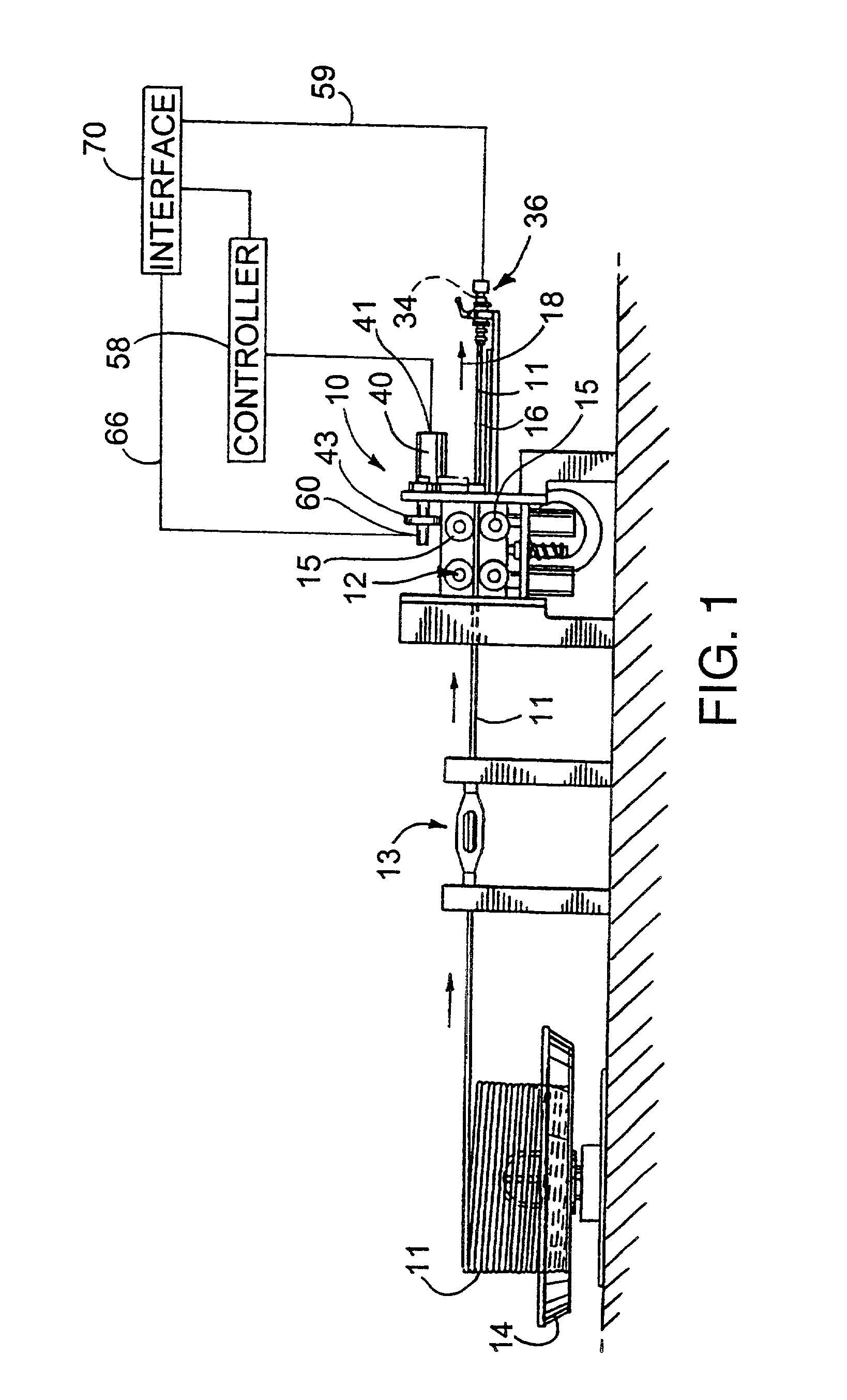
[0027] For purposes of illustration and referring to FIG. 1, the present invention has been shown in the drawings as incorporated in a cutting apparatus 10 for cutting off successive leading end portions of an elongated length of wire 11 adapted to be advanced along a predetermined wire path 18 (the wire path being shown schematically in FIG. 1 by arrows above the actual wire path which is occupied by the wire 11 to indicate direction of wire advancement). While the cutting apparatus 10 may be used in many different applications, it herein has been shown in conjunction with a feed mechanism 12 which pulls wire 11 through a wire straightening apparatus 13, that in turn is supplied with wire stock from an unwinding station 14, or from a wire drawing machine.

[0028] In the first embodiment, the feed mechanism 12, the straightening apparatus 13 and the wire supply and unwinding station 14 do not constitute part of the invention. It will suffice to say that the feed mechanism 12 includes ...

second embodiment

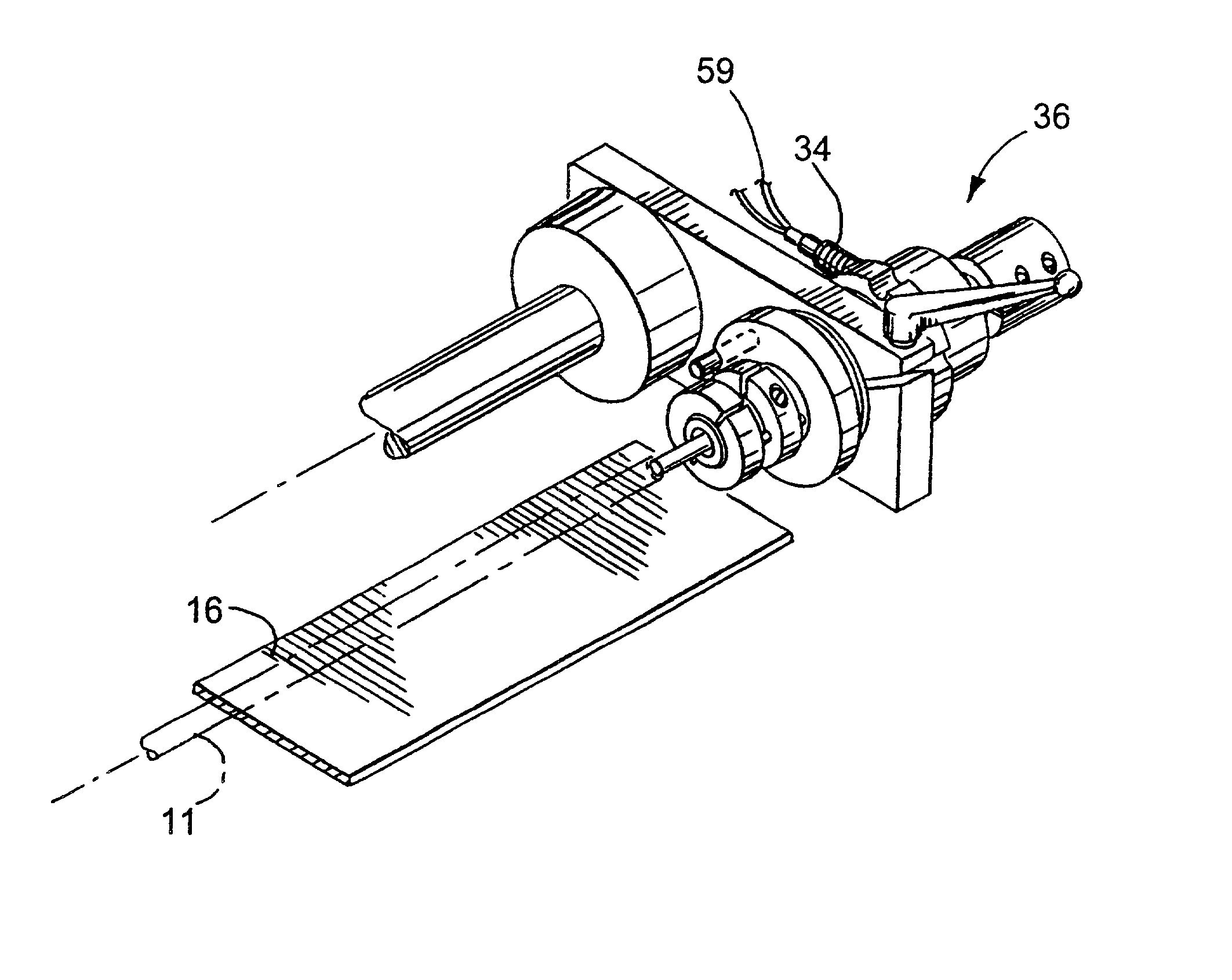
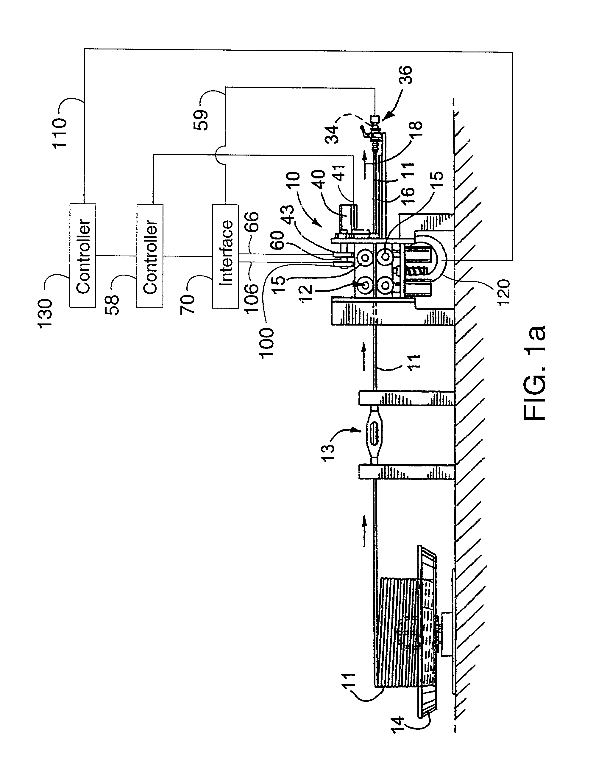
[0041] The first additional feature in the second embodiment is a third proximity sensor in the form of a proximity switch 100 that also senses position of the cutter 20 relative to the wire 11 or wire path 18. The proximity switch 100 includes a cam 102 mounted on the cutter shaft 44 and a stationary sensor element 104 to sense the position of the cam 62. The position of the cam 62 correlates to the position of the cutter 20. The cam 102 is offset from the angular position of the cam 62 of the other sensor 60 that also senses position of the cutter shaft 44 and hence the cutter position. In this manner the leading sensor 100 is used to indicate that the cutter shaft 44 and cutter 20 is near to the home position and serves to warn the controller 70 of the same. Once the leading sensor 100 sends a signal (either by sensing the presence or absence of metal of the cam 102 in which an off signal or on signal is provided) to the controller 70 via line 106 indicating the cutter 20 is clos...


PUM

PropertyMeasurementUnit
Lengthaaaaaaaaaa
Frequencyaaaaaaaaaa

Abstract

A clutchless wire cutting apparatus for successively cutting off leading end portions of a predetermined length of wire from a wire stock. The wire is advanced through a cutting station which includes the cutting apparatus. The cutting apparatus includes an electrical motor whose output is coupled to the cutter mechanism which performs the successive wire cuts. A proximity switch or sensor located downstream of the cutting station signals a controller each time the wire reaches the desired length to periodically generate an electrical current to the electrical motor for selectively intermittently driving the motor at a relatively high frequency corresponding to the frequency at which wire cuts are made. The motor may also be continuously driven for cutting shorter wire lengths. The motor has an output on an motor shaft which is coupled to a cutter shaft via a belt drive. The cutter shaft includes an eccentric cam which acts directly on the wire cutter. A proximity sensor or switch is also provided at the cutting station to determine the location of the wire cutter to provide a home position for the system.

Description

CROSS-REFERENCE TO RELATED PATENT APPLICATIONS[0001] This patent application is a continuation of copending continuation-in-part U.S. patent application Ser. No. 09 / 675,397, filed Sep. 29, 2000 [pending], which is a continuation-in-part of copending U.S. patent application Ser. No. 09 / 304,021, filed May 3, 1999 [pending].FIELD OF THE INVENTION[0002] The present invention generally relates to wire cutting apparatus and more particularly relates to the drive mechanics and control mechanisms for controlling the operation of a wire cutting apparatus.BACKGROUND OF THE INVENTION[0003] Wire manufacturers typically coil wire, usually of a predetermined number of lineal feet, onto relatively large spools or into coils. Before the wire is used or shipped to market, it is often necessary to cut the wire from the coil into shorter segments also of a predetermined length. In order to transform the wire from the curvilinear shape it assumes as a result of being coiled, a wire straightening appara...

Claims


Application Information

Patent Timeline
IPC IPC(8): B21F11/00B23D23/00
CPCB21F11/00B23D23/00Y10S83/907Y10T83/541Y10T83/531Y10T83/159Y10T83/515Y02P70/187Y02P70/10
Inventor KERN, MICHAELBURNS, IRVIN
Owner ROCKFORD MFG GROUP
Why Eureka
Try Eureka