DC bus boost method and system for regenerative brake

a dc bus and booster technology, applied in the direction of motor/generator/converter stopper, dynamo-electric converter control, transportation and packaging, etc., can solve the problems of high cost, high cost, and many extra components, and achieve less expensive components, simple operation, and more energy efficient switching activity.

Active Publication Date: 2011-05-05
ROCKWELL AUTOMATION TECH
View PDF2 Cites 16 Cited by
  • Summary
  • Abstract
  • Description
  • Claims
  • Application Information

AI Technical Summary

Benefits of technology

[0003]Embodiments of the present invention provide novel techniques for using a fundamental front end (FFE) rectifier to provide for AC rectification, regenerative braking, and DC voltage boosting. The FFE rectifier is simple to operate, uses less expensive components, and is more energy efficient in its switching activity than other types of switched converters. In particular, the FFE rectifier can incorporate a low impedance reactor (typically 3% impedance) and exhibits less energy loss due to switching than comparable rectifiers such as active front end (AFE) rectifiers. Cost can be minimized by reducing the number of system components and by lowering the operational expenses where possible.

Problems solved by technology

However, one drawback of electric motor drives that provide for motor drive, regenerative braking, and DC voltage boosting is that they require many extra components, lose energy due to constant switching activity, and are costly.

Method used


Image

  • DC bus boost method and system for regenerative brake
  • DC bus boost method and system for regenerative brake
  • DC bus boost method and system for regenerative brake

Examples


Embodiment Construction

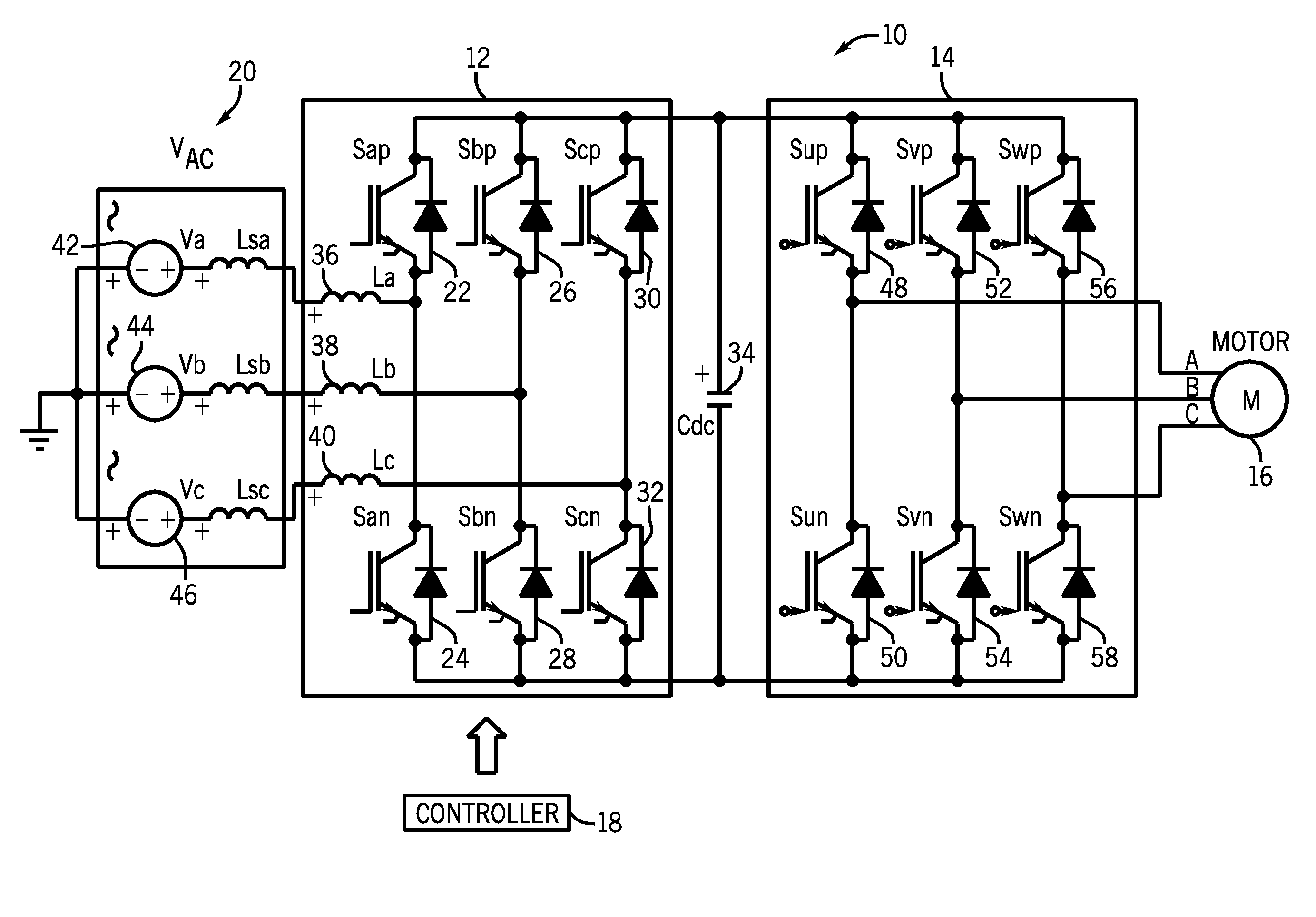
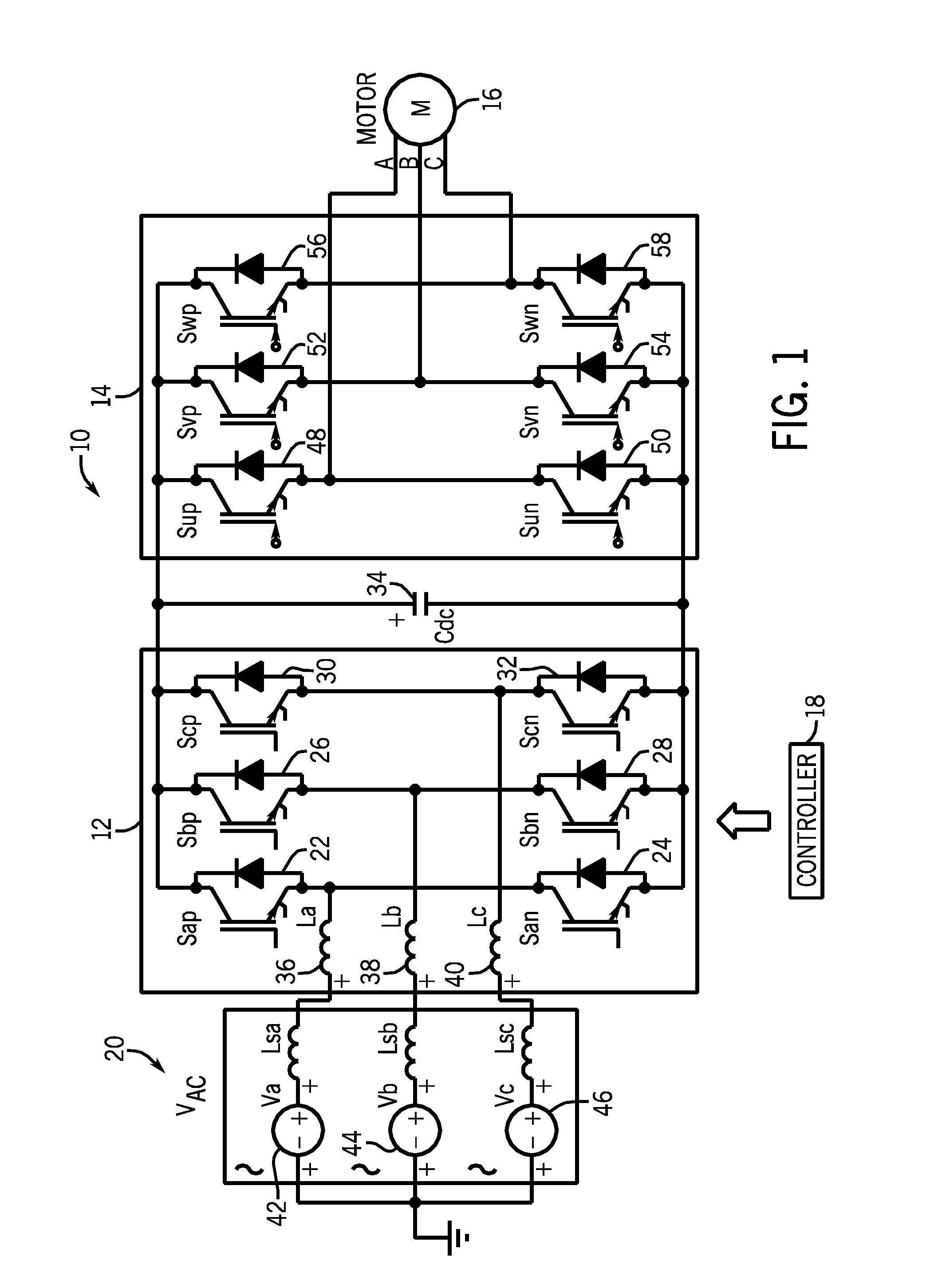
[0015]FIG. 1 illustrates an embodiment of a three-phase motor controller 10. The three-phase motor controller 10 may include an insulated gate bipolar transistor (IGBT) rectifier circuit 12 coupled to an inverter circuit 14, which may be used to drive a three-phase motor 16. In the illustrated embodiment, the rectifier circuit and the inverter circuit are controlled by a controller 18. Three phases of AC voltage from the supply mains 20 are converted into DC voltage by the rectifier 12. The DC voltage is then converted to controlled frequency AC voltage by the inverter circuit 14 to drive the motor 16. In one embodiment of the invention the rectifier 12 may provide for AC rectification, braking regeneration, and DC voltage boosting. The rectifier circuit 12 comprises a set of solid state switches Sap 22, San 24, Sbp 26, Sbn 28, Scp 30, and Scn 32, each provided with a fly-back diode. In the present discussion, the subscripts “a”, “b” and “c” are used to designate each of three phase...


PUM


Abstract

Embodiments of the present invention provide novel techniques for using a switched converter to provide for three-phase alternating current (AC) rectification, regenerative braking, and direct current (DC) voltage boosting. In particular, one of the three legs of the switched converter is controlled with a set of pulse width modulation (PWM) control signals so that the input AC phase having the highest voltage is rectified and one of the switches in the two other legs is turned on to allow for added voltage. This switching activity allows for voltage from multiple AC line mains to be combined, resulting in an overall boost of the DC voltage of the rectifier. The DC voltage boost can then be applied to the common DC bus in order to ameliorate voltage sags, help with motor starts, and increase the ride-through capability of the motor.

Description

BACKGROUND[0001]The present invention relates generally to the field of electric motor drives such as those used to control electric motors and similar loads. More particularly, the present invention relates to systems and methods for using switched converters to rectify alternating current (AC) into direct current (DC), boost the overall voltage of a DC bus, and provide for regenerative braking capabilities while reducing the number of components in the system.[0002]Power rectifier systems are used in a wide range of applications. For example, power converters that perform rectification are used with centrifuges, magnetic clutches, pumps and more generally, in electric motor drive controllers to rectify and condition incoming AC voltage and to supply DC voltage to the motor. Many electric motor controllers also include some type of motor braking ability, in which energy from the motor is re-converted while slowing the driven load. The energy resulting from the braking operation can...

Claims


Application Information

Patent Timeline
Patent Type & Authority Applications(United States)
IPC IPC(8): H02P27/00H02P3/14
CPCH02M1/083H02M5/4585H02M2007/2195H02P23/06Y02T10/642H02P27/08B60L2210/20Y02T10/725H02P25/105H02M7/2195Y02T10/64Y02T10/72
Inventor WEI, LIXIANGLUKASZEWSKI, RICHARD A.KERKMAN, RUSSELSEIBEL, BRIAN J.
Owner ROCKWELL AUTOMATION TECH
Why Eureka
Try Eureka