Passively-thermally-stabilized photonic apparatus, method, and applicatons

Active Publication Date: 2011-05-05
CORNELL UNIVERSITY
View PDF21 Cites 36 Cited by
  • Summary
  • Abstract
  • Description
  • Claims
  • Application Information

AI Technical Summary

Benefits of technology

[0010]An embodiment of the invention is a photonic apparatus, comprising an interferometer having a second arm, wherein the interferometer is characterized by a negative net optical path length change as a function of temperature, δLM/δT; and a waveguide closed loop resonator characterized by a positive optical path length change as a function of temperature, δLR/δT, disposed in light-coupling proximity to the second interferometer arm, wherein the absolute value of δLM/δT is equal to the absolute value of δLR/δT, such that the apparatus is characterized by a resonance having substantially no spectral shift as a function of temperature, wherein the apparatus is an athermal/temperature insensitive, resonant photonic device. According to an aspect, the interferometer further comprises a first waveguide arm having a length L1 wherein at least a portion of the first waveguide arm, L1W(1), has a width w1, and an effective mode index neff(1); and, wherein the second arm is a waveguide having a length L2 and a width w1, wherein at least a portion of the second waveguide arm, L2W(2), has a maximum width w2 that is less than w1 over L2W(2), and the second waveguide arm is optically coupled to the first waveguide arm, further wherein the interferometer is characterized by an effective mode index neff(2), where |L2−L1|=ΔL≠0, L2W(2)=L1W(1), w1−w2=Δw, and |neff(2)−neff(1)|=Δneff≠0. The second waveguide arm may be tapered over transition regions between L2 and L2W(2). In a non-limiting aspect, the interferometer is a waveguide-based Mach-Zehnder interferometer (MZI). In a non-limiting aspect, the closed loop waveguide resonator is a ring resonator having a radius, R. In a non-limiting aspect, the interferometer and the closed loop resonator are integrated on a chip. In a non-lim

Problems solved by technology

However ultralow power photonic interconnects compatible with current CMOS microelectronics have not yet been demonstrated, mainly because the power needed to stabilize these photonic components with temperature is prohibitively high, due to the high thermo-optic coefficient of silicon.
Most

Method used


Image

  • Passively-thermally-stabilized photonic apparatus, method, and applicatons
  • Passively-thermally-stabilized photonic apparatus, method, and applicatons
  • Passively-thermally-stabilized photonic apparatus, method, and applicatons

Examples


Embodiment Construction

[0033]Reference will now be made in detail to non-limiting, exemplary embodiments of the invention along with examples as illustrated in the accompanying drawings. Wherever possible, the same reference numbers will be used throughout the drawings to refer to the same or like parts.

Mach-Zehnder Interferometer (MZI) with Negative Temperature Sensitivity

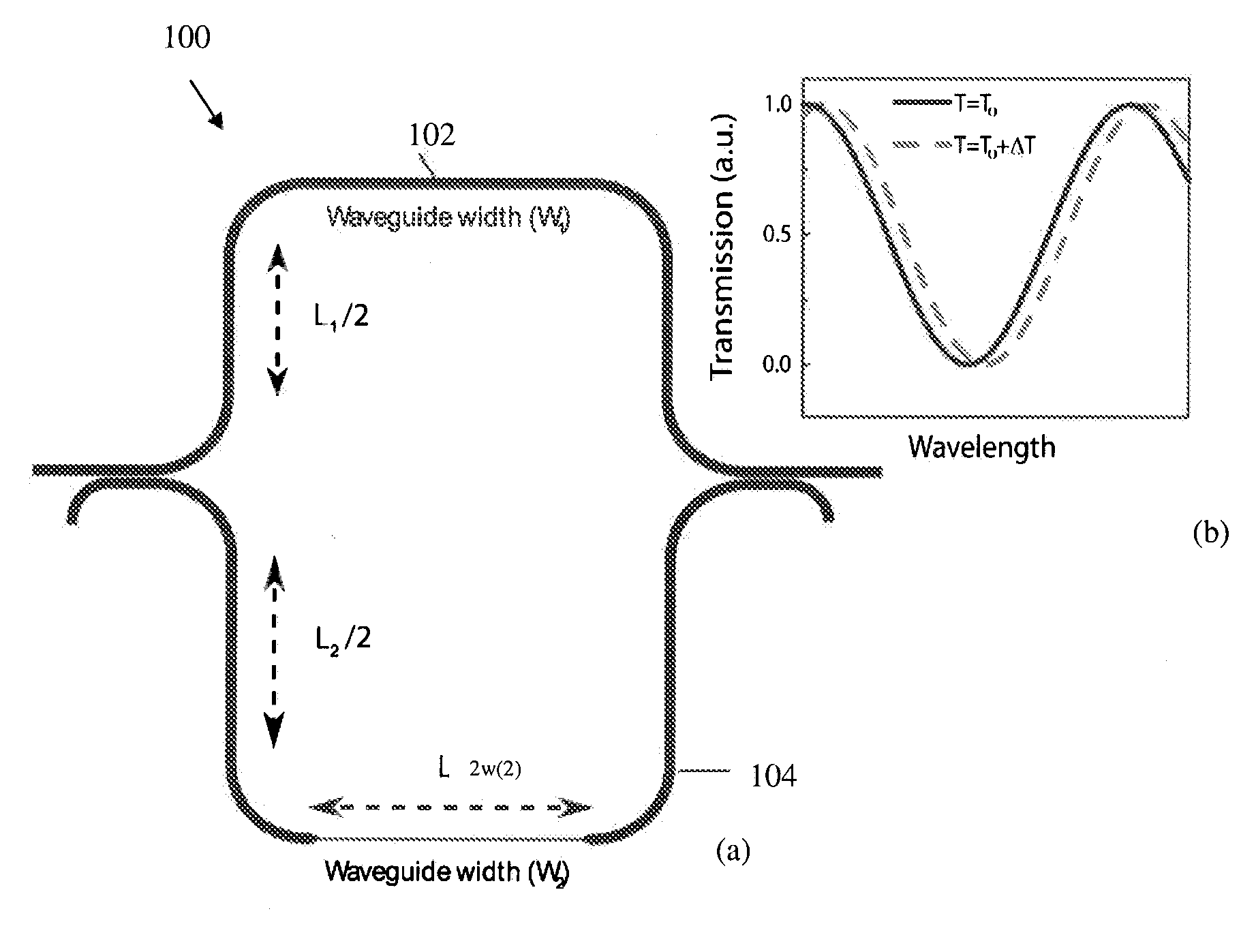
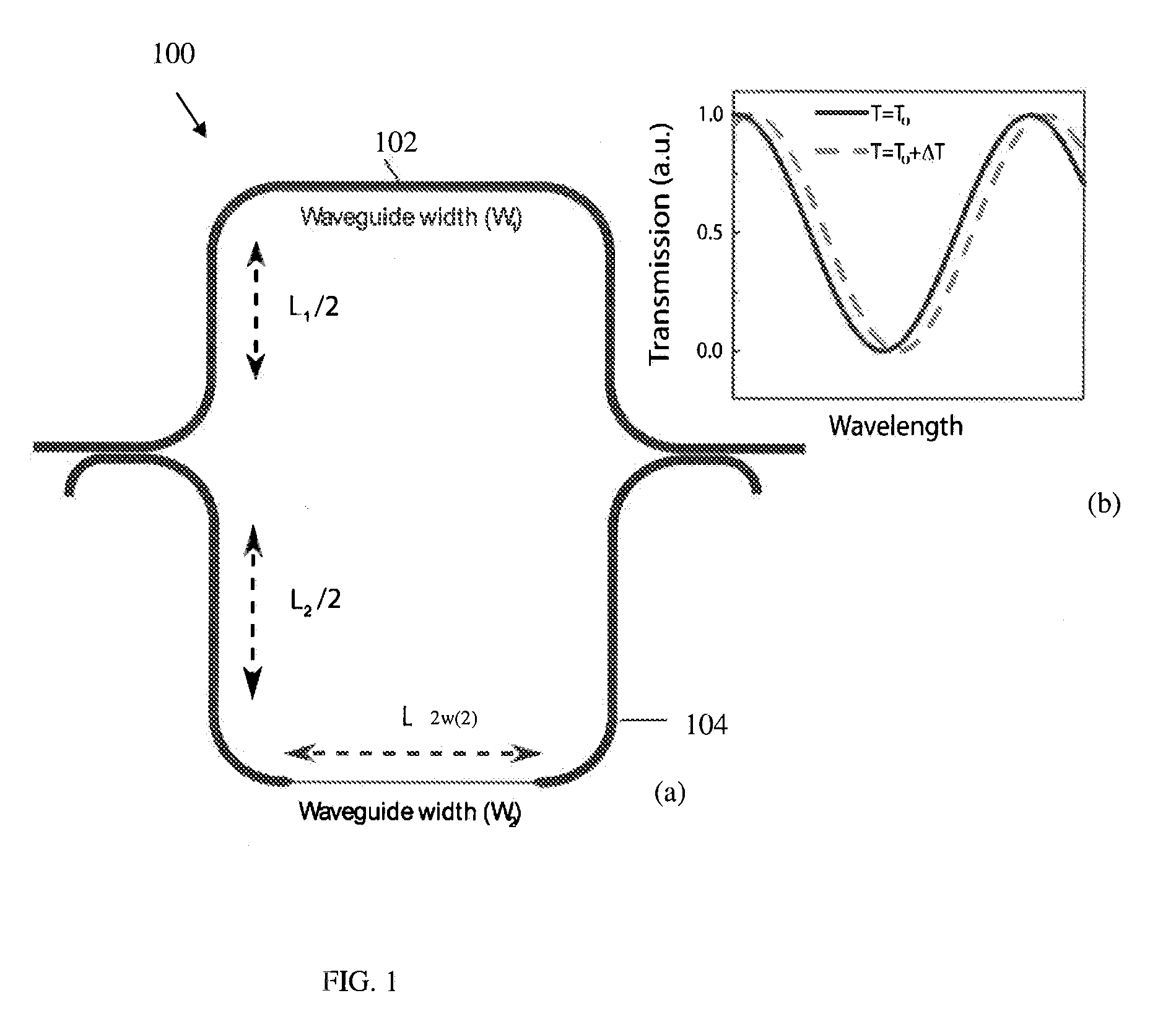
[0034]A Mach-Zehnder interferometer 100 having negative temperature sensitivity is schematically illustrated in FIG. 1. The exemplary MZI 100 is a waveguide-based MZI fabricated on a silicon-on-insulator wafer, as described in more detail below. The MZI includes a first waveguide arm 102 having a length L1 and a width w1 typically over its entire length but at least over a portion denoted L1W(1), and an effective mode index neff(1); and, a second waveguide arm 104 having a length L2 and a width w1 over a portion of L2, and a maximum width w2 that is less than w1 over a portion L2W(2). The second waveguide arm is optically coupled to the...


PUM


Abstract

Apparatus and methods that compensate for the thermally-induced drift of the resonance frequency of a closed-loop resonator include, in an exemplary embodiment, a waveguide-based Mach-Zehnder interferometer (MZI) and an overcoupled, waveguide-based microring resonator. The temperature-induced red-shifting ring resonance can be balanced by a spectral blueshift with temperature of the MZI. To stabilize the resonance of the ring at a given wavelength, the change in optical path lengths with temperature of the ring and the MZI should be equal and opposite. The interplay of nonlinear change in phase of ring resonator with temperature and linear change in phase of MZI with temperature, along with matching the period of this phase change, gives rise to perfect oscillation in the combined system resonance with temperature.

Description

CROSS-REFERENCE TO RELATED APPLICATIONS[0001]This application claims priority to U.S. provisional Patent Application Ser. Nos. 61 / 263,575 filed on Nov. 23, 2009, 61 / 257,144 filed on Nov. 2, 2009, and 61 / 258,383 filed on Nov. 5, 2009, the subject matter of all of which are incorporated herein by reference in their entireties.FEDERALLY SPONSORED RESEARCH[0002]This invention was made with government support under Project ID No. 0446571 awarded by the National Science Foundation. The government has rights in this invention.BACKGROUND OF THE INVENTION[0003]1. Field of the Invention[0004]Embodiments of the invention relate generally to photonic components, more particularly to passively-thermally-stabilized, ultra low power photonic interconnect apparatus and methods and, even more particularly to CMOS (Complementary Metal-Oxide-Semiconductor)-compatible apparatus, methods, and applications thereof.[0005]2. Technical Background[0006]Si nanophotonics enables CMOS-compatible systems consist...

Claims


Application Information

Patent Timeline
IPC IPC(8): G01B9/02
CPCG02B6/12007G02B6/29353G02B6/29343
Inventor LIPSON, MICHALGUHA, BISWAJEET
Owner CORNELL UNIVERSITY
Why Eureka
Try Eureka