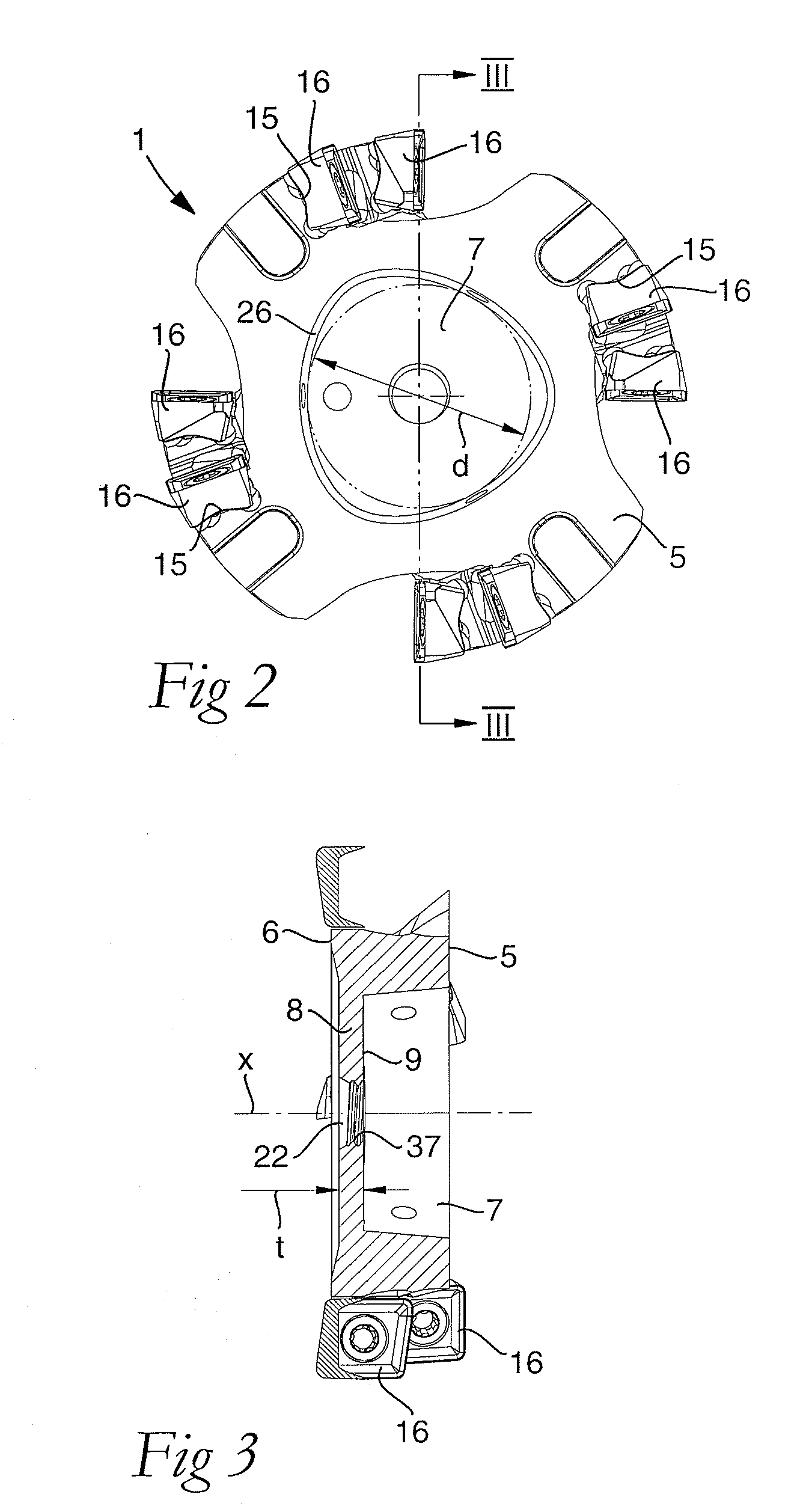
[0010]An object is achieved by a tool of the type indicated and that the wall section is elastically flexible and, by the contractive force in the mounted state, bent toward the end surface. By such an elastic wall section, accordingly a contractive force is provided that exerts a prestress on the fastening element, which contributes to the fastening element being reliably secured. The prestress prevents the fastening element from coming loose even if the tool vibrates during use. Due to the elastic wall section, a relatively short fastening element, for instance, a relatively short fixing screw having a
short length extension, can thus be used because the fastening element does not need to have any inherent elasticity. Thus, space can be saved in the longitudinal direction of the tool. Temperature differences during use of the tool can be mastered in an advantageous way. Due to the elastic wall section, the tool parts will be pressed against each other under all operation conditions, i.e., in all temperatures occurring in use. Thereby, it is avoided that the fastening element comes loose, or is poorer secured, as a consequence of expansion or contraction of the material in the tool parts because of temperature variations.
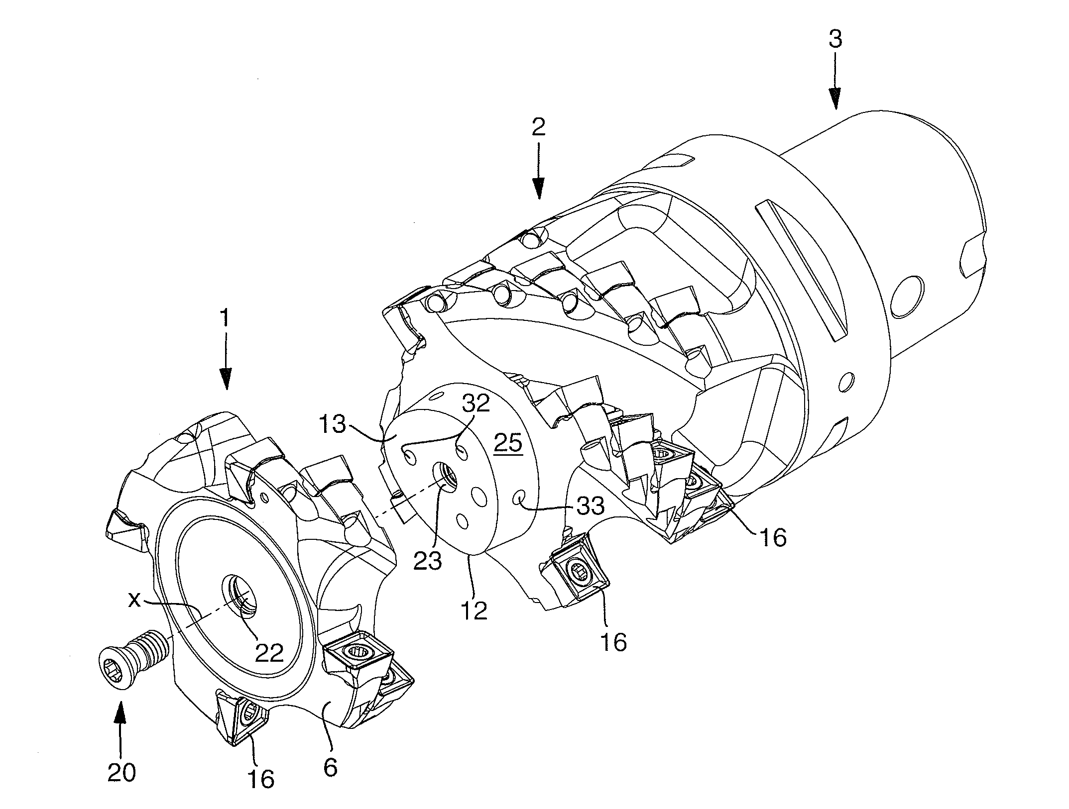
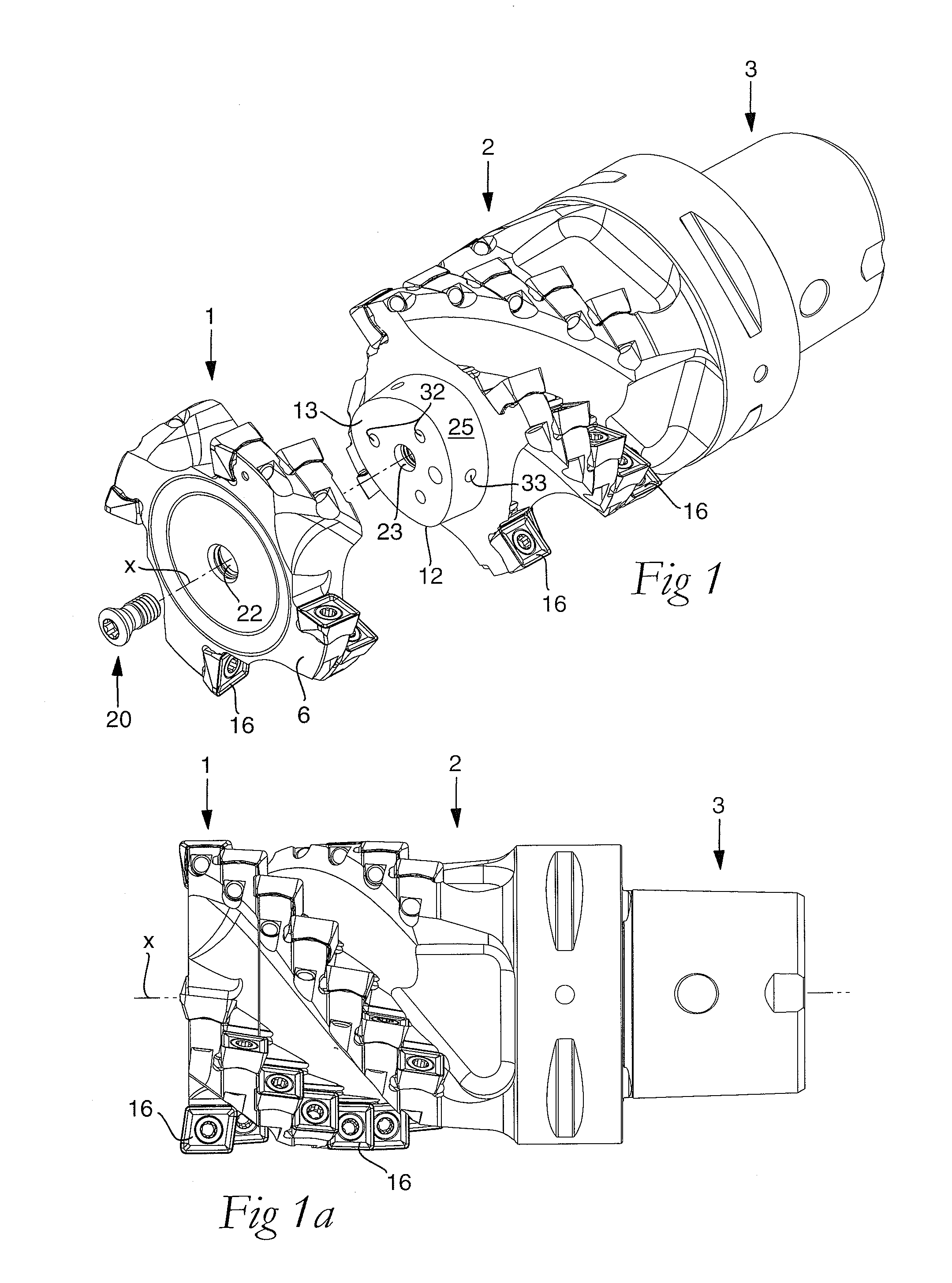
[0011]The primary and secondary tool parts can be mounted and dismounted in a simple way by the fastening element that, for instance, may be a fixing screw that extends through the wall section and into a thread of the protuberance. Thus, one of the tool parts can quickly and simply be replaced in the event of rupture and the other non damaged tool part can be kept.
[0014]According to one embodiment of the invention, the protuberance has a circumference surface that tapers toward the end surface and the recess a corresponding inner surface that tapers toward the bottom surface, the circumference surface and the inner surface forming an angle α with the center axis. Such a tapering, or conical, design of the circumference surface and the inner surface also contributes to a reliable mounting of the two tool parts to each other. Advantageously, the angle α may be ≦10°, preferably ≧2° and ≦7°, more preferably ≧3° and ≦6°.
[0015]According to one embodiment of the invention, the primary connecting surface, in the mounted state, faces the secondary connecting surface, the primary tool part and the secondary tool part being dimensioned in such a way that a second gap is formed between the primary connecting surface and the secondary connecting surface in the mounted state. Due to this design, with the first gap and the second gap, the two tool parts will abut against each other only by the tapering or conical circumference surface of the protuberance and the tapering or conical inner surface of the recess. Thus, the second gap contributes to a reliable
interconnection of the two tool parts. Furthermore, the second gap in co-operation with the elastic wall section contributes to somewhat reduced tolerance requirements of the tool parts, and more precisely of the two connecting surfaces, the circumference surface of the protuberance and the inner surface of the recess. Due to the lower tolerance requirements, the manufacture can be facilitated and made in one or more
machine operations in one and the same set-up. No finishing in the form of
grinding or the like is required for the completion of the tool parts and the surfaces thereof.
[0017]According to one embodiment of the invention, the fastening element includes a screw, which extends through an opening of the wall section and is in engagement with a threaded hole of the protuberance. Such a screw guarantees a simple mounting and dismounting of the two tool parts. The screw may advantageously be relatively short, as was mentioned above, for instance, having a length /
diameter ratio of 1 / 1-4 / 1.
[0020]According to one embodiment of the invention, the secondary tool part includes a central cavity formed for the
receipt of a damping mechanism. It is technically advantageous if the damping mechanism can be applied as far forward as possible in the tool, i.e., as near the opposite surface of the primary tool part as possible. In this embodiment, this surface forms the distal end surface of the tool that is located where the maximum deflection occurs during use of the tool. Because the primary tool part has a relatively
thin wall section and because the fixing screw can be made relatively short, the central cavity can extend far forward in the tool, which allows the damping mechanism to be positioned in the vicinity of the distal end surface.

