Method for molding molded foam, and molded foam

a technology of molded foam and molded foam, which is applied in the direction of liquid handling, closure using stoppers, other domestic articles, etc., can solve the problems of significantly deteriorating impact resistance, adverse expansion ratio, and cell surface breakage, and achieve excellent heat insulation property and impact resistance. , the effect of high expansion ratio

Active Publication Date: 2011-05-05
KYORAKU CO LTD
View PDF3 Cites 47 Cited by
  • Summary
  • Abstract
  • Description
  • Claims
  • Application Information

AI Technical Summary

Benefits of technology

[0014]In view of the problems described above, an object of the present invention is to provide a molded foam molding method capable of obtaining a molded foam in which a pinhole may not be formed with ease even when a foamed resin expands largely in molding and which has a high expa

Problems solved by technology

Such a conventional technique has the following problem.
Consequently, surfaces of the cells become broken and an expansion ratio adversely decreases.
In the foaming and blow molding in Patent Document 2, however, the polypropylene having a long chain branching structure causes the following problem.
In addition, the molded foam using the polypropylene having a long chain branching structure has a problem of considerably deteriorated impact resistance.
Because of the circumstances desc

Method used


Image

  • Method for molding molded foam, and molded foam
  • Method for molding molded foam, and molded foam
  • Method for molding molded foam, and molded foam

Examples


example 1

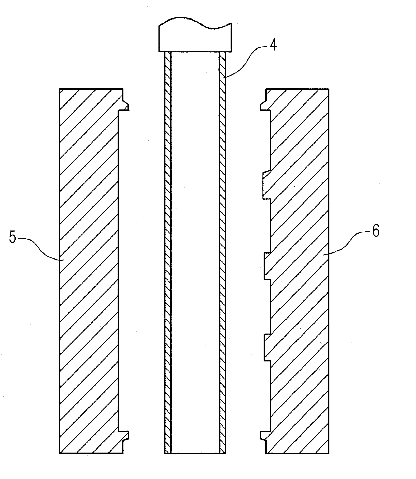
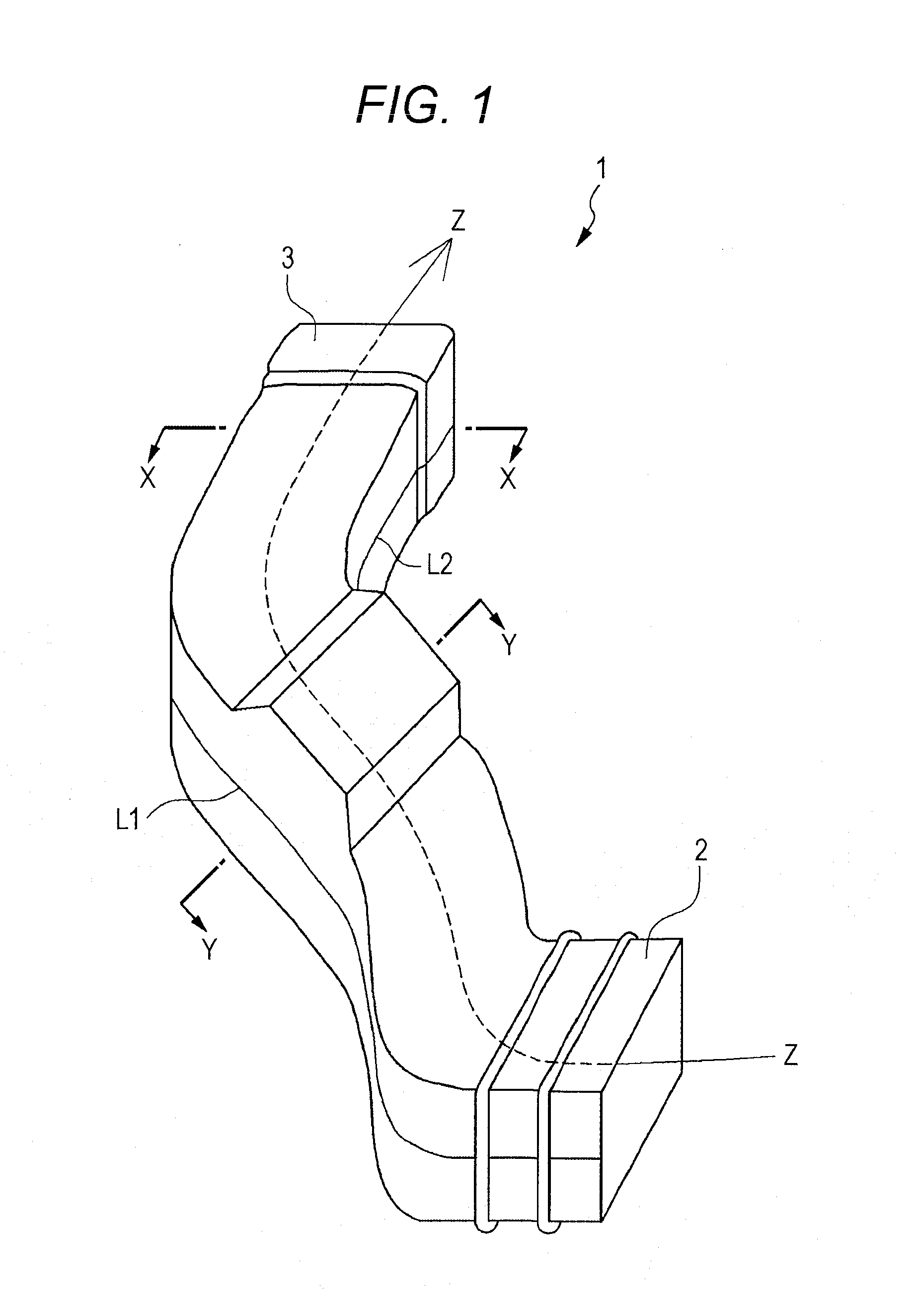
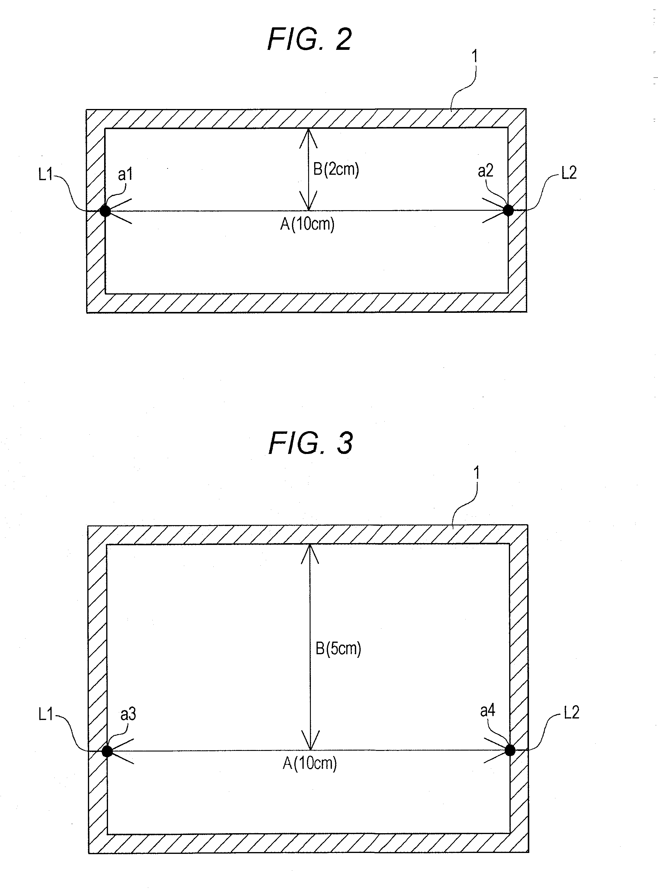
[0067]As a polypropylene-based resin, a blend (equilibrium compliance: 2.0×10⁻³×Pa−1) of 30 wt % of propylene homopolymer having a long chain branching structure in which an MFR at 230° C. is 2.1 g / 10 minutes (Daploy WB130 provided by Borealis AG) and 70 wt % of crystalline ethylene-propylene block copolymer in which an MFR at 230° C. is 0.5 g / 10 minutes (NOVATEC EC9 provided by Japan Polypropylene Corporation) was used. To this blend, a foaming agent and 0.8 parts by weight (in terms of talc) of a talc masterbatch (MAT360H provided by Shiraishi Calcium Kaisha, Ltd.) as a foaming core agent were added. Then, the blend was kneaded in an extruder and retained in an accumulator. Subsequently, after a predetermined amount of resin is retained, a foamed cylindrical parison was extruded from a die slit by pressing a piston of the accumulator. The parison was then inserted into a vehicle duct mold having a portion where a blow ratio is 0.7, so that a molded foam having an average thickness...

examples 2 to 7

[0068]Similarly to Example 1, a molded foam was obtained using a blend having a compounding ratio shown in Table 1. In particular, in cases of Examples 2, 4, 5 and 6, a regrind of a molded foam was reused and blended into a raw material so as to be 70 wt % in the entire blend. According to any of Examples 2 to 7, no pinhole is formed even when a maximum blow ratio is 0.4. Further, since an impact strength is not less than 30 kg·cm, there was no possibility of causing cracking when a vehicle vibrates or when vehicle components are assembled or transported. Moreover, since an expansion ratio was not less than 1.5 times, a heat insulating property was sufficient.


PUM

PropertyMeasurementUnit
Fractionaaaaaaaaaa
Fractionaaaaaaaaaa

Abstract

The invention provides a molded foam molding method capable of obtaining a molded foam in which pinholes may not be formed with ease even when a blow ratio is high and which has a high expansion ratio. The invention also provides a molded foam which includes no pinholes, is reduced in weight, and is excellent in heat insulating property. The molding method includes blending a polypropylene-based resin having an equilibrium compliance from 2.0 to 6.0 (10−3×Pa−1) with a foaming agent and kneading the blend in an extruder. The extruded foamed resin is molded so as to be fit along a mold by a pressurized fluid. Moreover, the molded foam is formed by the method described above, and has an expansion ratio from 1.5 to 5.0 times and an impact strength of not less than 30 kg·cm.

Description

CROSS-REFERENCE TO RELATED APPLICATION[0001]This application is based on Japanese Patent Application No. 2009-251557 filed with the Japan Patent Office on Oct. 31, 2009, the entire content of which is hereby incorporated by reference.BACKGROUND[0002]1. Technical Field[0003]The present invention relates to a method for molding a molded foam for use in, e.g., a climate control duct for vehicles, and such a molded foam.[0004]2. Related Art[0005]A conventional molded foam molding method involves melting and kneading a foaming agent and a base resin by an extruder, extruding the blend through a die to mold the blend into a foamed parison in a cylinder shape, clamping split mold blocks with the parison inserted therebetween, and subjecting the parison to blow molding by blowing a pressurized gas into the parison (refer to Patent Document 1). Herein, a polypropylene-based resin is used as the base resin in consideration of heat resistance, rigidity and the like regarding the molded body.[0...

Claims


Application Information

Patent Timeline
IPC IPC(8): B32B1/08B29C44/00B29C49/04C08F10/06
CPCB29C44/50B29C49/0005B29K2023/12B29K2105/04B29L2023/004Y10T428/1352C08J9/06C08J2201/03C08J2323/12Y10T428/1376B29L2031/3055B29C44/505B29C49/087B29C2049/7879
Inventor ONODERA, MASAAKISUMI, TAKEHIKOTAMADA, TERUOIGARASHI, YUOHNO, YOSHINORI
Owner KYORAKU CO LTD
Why Eureka
Try Eureka