Inductive coagulation sensors and devices

a technology of inductive coagulation and sensors, applied in the direction of resistance/reactance/impedence, instruments, material analysis, etc., can solve the problem of plasma clot, and achieve the effect of enhancing accuracy and sensitivity of sample analysis

Active Publication Date: 2011-05-12
MICROPOINT BIOTECHNOLOGIES CO LTD
View PDF9 Cites 8 Cited by
  • Summary
  • Abstract
  • Description
  • Claims
  • Application Information

AI Technical Summary

Benefits of technology

[0013]In still other aspects, the inductive sensor can have field and sensor inductors coupled essentially only through the sample. For example, the sensor can include a conductivity sensor having a sample conduit with a central axis, a first inductive coil of conductive material coiled around the sample conduit at a first position, a second inductive coil of conductive material coiled around the sample conduit at a second position separated from the first position by a sample space distance along the axis, a sample chamber in the conduit in the region of the sample space separation, and an electric field shield between the inductors, wherein the shield does not directly block electric fields in the sample space between the inductors. In this way, a conductive fluid in the sample space will be inductively coupled to the first inductive coil and inductively coupled to the second coil. This configuration can enhance the relative influence of sample counter-emf fields on the sensor inductor over primary field inductor fields. For example, the shield reduces or eliminates the phenomenon of field inductor field lines reaching the sensor inductor without going through the sample or being modulated by fields induced in the sample. In preferred embodiments, the shield is positioned to block relatively less inductive interaction with the sample than it blocks between the inductors.
[0016]In many embodiments, the device further includes an electric field shield between the first and second inductors. Optionally, the inductors and / or sample chamber is shielded to reduce background noise from extraneous fields. Alternately, first (field) inductor is inductively coupled to the second (sensor) inductive coil.
[0024]In certain preferred embodiments, accuracy and sensitivity of a sample analysis can be enhanced by comparing inductive effects on the test conductive fluid to inductive effects on a control fluid. In many embodiments, it is preferred to include at least high and low calibration reference standard samples in additional sample chambers to confirm the assay is reading accurately across the useful range.DEFINITIONS

Problems solved by technology

A reagent can cause the plasma to clot.

Method used


Image

  • Inductive coagulation sensors and devices
  • Inductive coagulation sensors and devices
  • Inductive coagulation sensors and devices

Examples


example

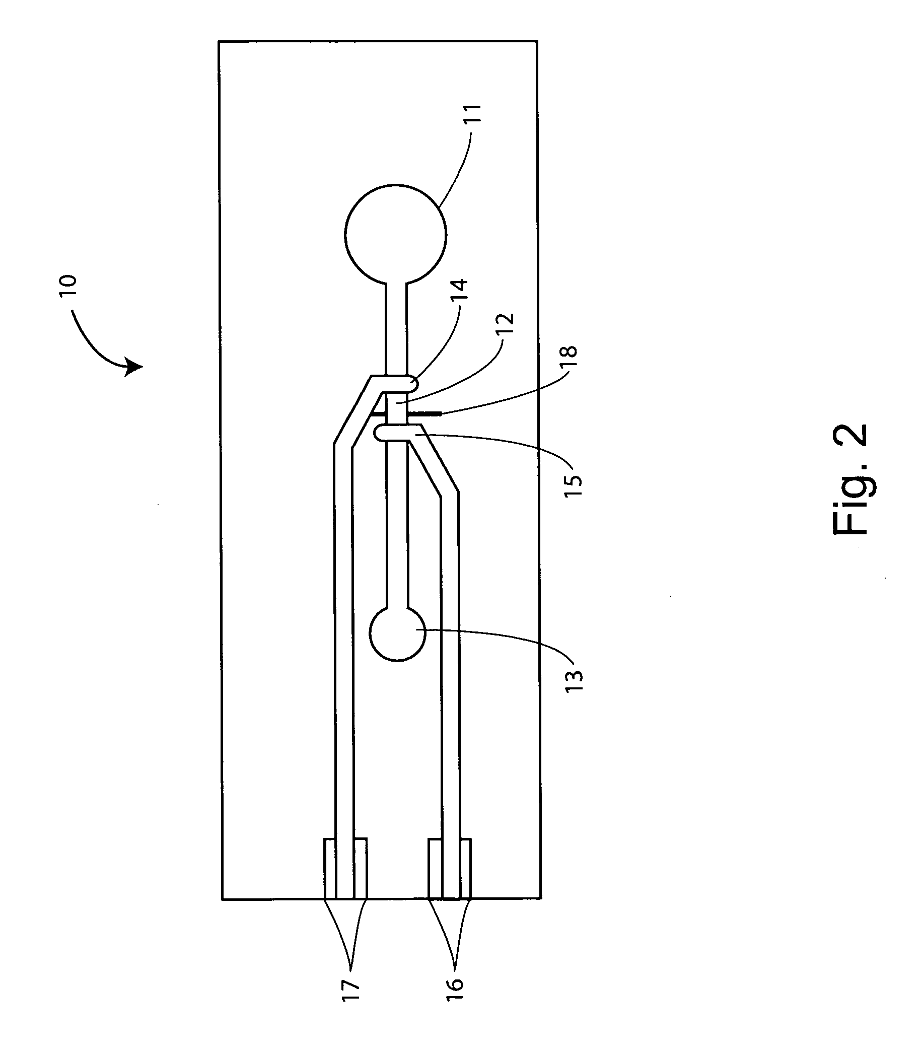
Prothrombin Time (PT) in a Micro-Scale Device

[0099]The following examples are offered to illustrate, but not to limit the claimed invention.

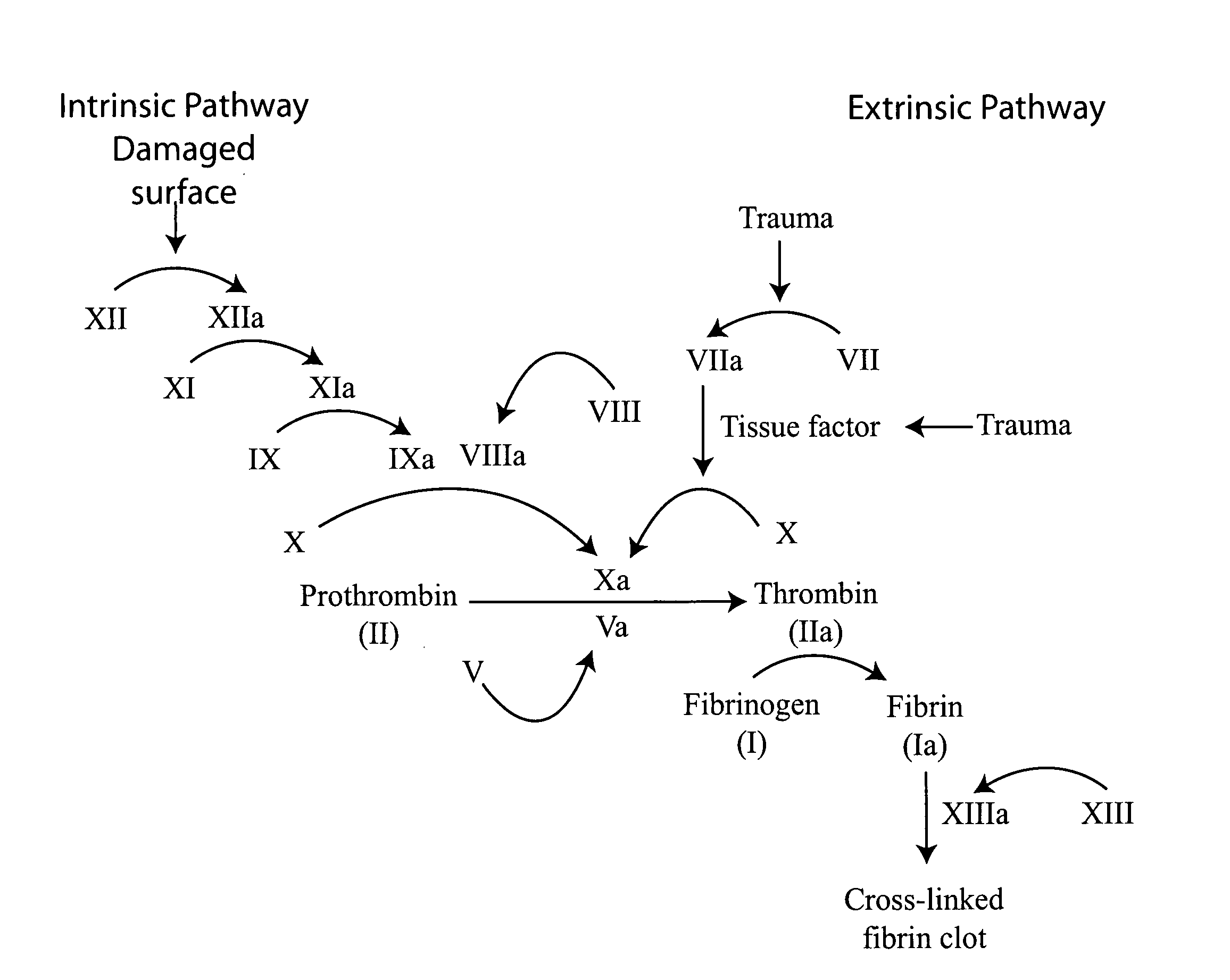
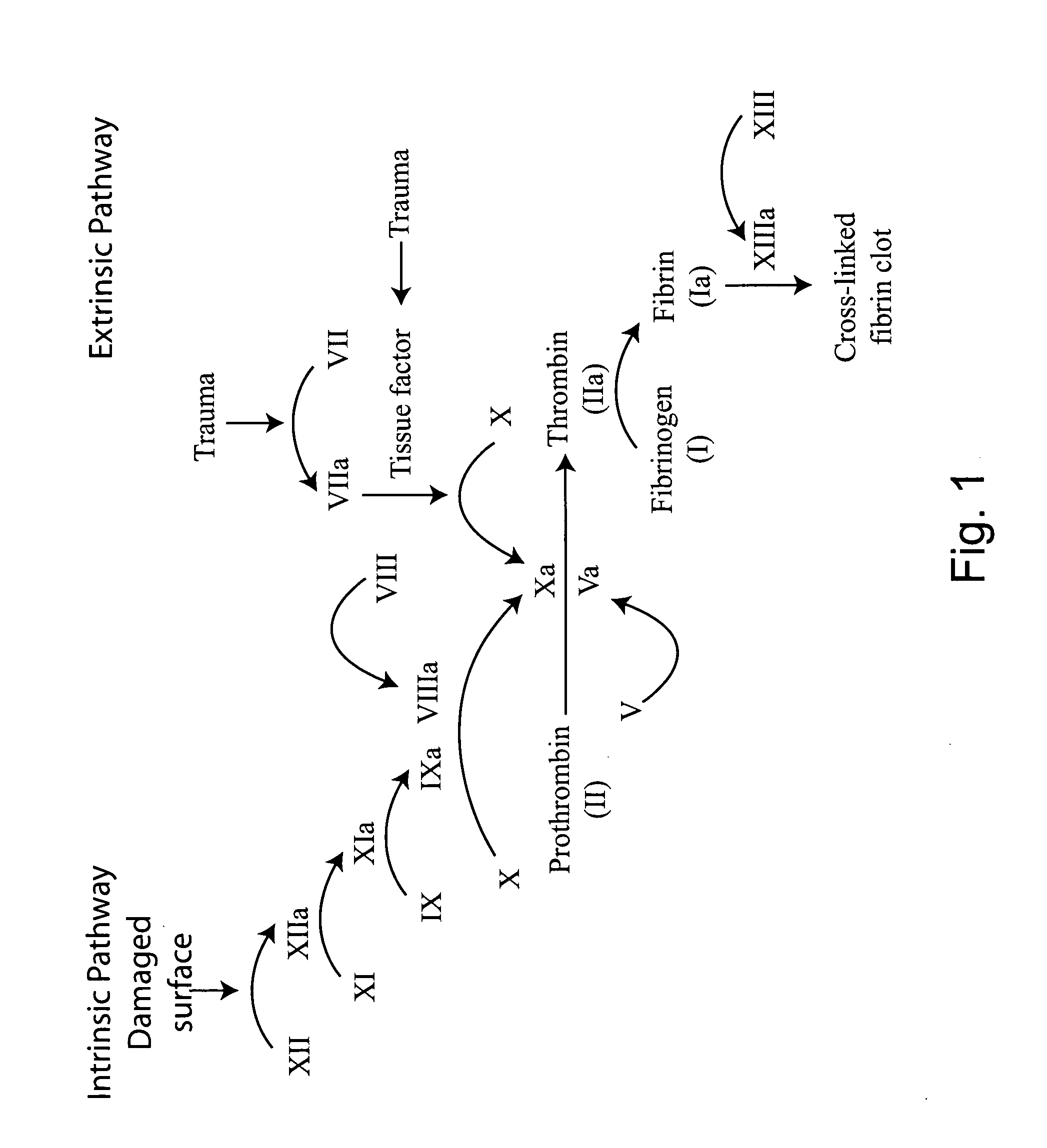
[0100]The prothrombin time (PT) measures the function of the coagulation extrinsic pathway. In a clinical setting, the PT is used to determine the clotting tendency of blood, monitor warfarin dosage, to detect liver disease, and can suggest a vitamin K deficiency. The normal range for prothrombin time is usually around 12-15 seconds.

[0101]In a standard PT assay time, blood is drawn into a test tube containing liquid citrate, which acts as an anticoagulant by binding the calcium in a sample. The blood is mixed, then centrifuged to separate blood cells from plasma. An excess of calcium is added (thereby reversing the effects of citrate), along with tissue factor (also known as factor III or thromboplastin). The time the sample takes to clot at 37° C. is traditionally detected mechanically or optically.

[0102]A PT can be determined using the methods...


PUM


Abstract

This invention provides methods and devices for detecting the viscosity and conductivity of a conductive fluid sample. A sample fluid can be received into a sample chamber between a field inductor and sensor inductor. Electromagnetic fields generated by the field inductor can be modulated due to the counter-emf induced in the sample. The modulations can be detected by the sensor inductor and correlated to electric parameters in the fluid.

Description

CROSS-REFERENCE TO RELATED APPLICATIONS[0001]This application claims priority to and benefit of a prior U.S. Provisional Application No. 61 / 278,665, Inductive Coagulation Sensors and Devices, by Michael Huang, et al., filed Oct. 9, 2009. The full disclosure of the prior application is incorporated herein by reference.FIELD OF THE INVENTION[0002]The invention is directed to devices and methods for detecting physical and electrical parameters of a conductive fluid. Exemplary devices include a sample chamber between a field inductor and a sensor inductor. The field inductor can be energized by an oscillator, and electromagnetic signals received by the sensor inductor can be detected by a voltage or current detector. Viscosity of a conductive fluid is measured by exposing the fluid to an electromagnetic field from a field inductor and monitoring currents, voltages or waveforms induced in the fluid. The fluid can be monitored by a sensor inductor in association with a detector. Viscosity...

Claims


Application Information

Patent Timeline
Patent Type & Authority Applications(United States)
IPC IPC(8): G01R27/28
CPCG01N11/00G01N33/4905G01R27/2611G01N2011/0066G01N33/86
Inventor HUANG, MICHAELWU, MENGYAWU, MENGYOU
Owner MICROPOINT BIOTECHNOLOGIES CO LTD
Why Eureka
Try Eureka