
Electronic endoscope system, processing apparatus for electronic endoscope, and image processing method

a technology of electronic endoscopy and processing apparatus, which is applied in the field of electronic endoscopy system, processing apparatus for electronic endoscopy, image processing method, can solve the problems of inability to easily compare inability to easily observe two images at a glance, and large amount of information in the broadband imag

Active Publication Date: 2011-05-12
FUJIFILM CORP
View PDF13 Cites 37 Cited by
  • Summary
  • Abstract
  • Description
  • Claims
  • Application Information

AI Technical Summary

Benefits of technology

An object of the present invention is to provide an electronic endoscope system for performing image processing, with high accuracy and without causing loss of at-a-glance property and contrast, to a blood vessel region located at a specific depth or to a region other than the blood vessel region in an image captured with an electronic endoscope, a processing apparatus for the electronic endoscope, and an image processing method.
It is preferable that the image processing is reduction of visibility. It is preferable that to the reduction of the visibility is to reduce contrast.
According to the present invention, the depth correlation information of the blood vessel depth relative to the brightness ratio between the broadband image data and the narrow band image data or the brightness ratio between the blue color signal and the green color signal of the mixed image data is used. Accordingly, the specific blood vessel region located at a desired depth is extracted accurately. Image processing, for example, contrast reduction processing is performed to the specific blood vessel region, for example, a surface blood vessel or a region other than the specific blood vessel region on the broadband image (visible light image). Thus, an endoscopic image in which the surface blood vessel or the region other than the surface blood vessel is easily observable is obtained.

Problems solved by technology

Accordingly, the two images cannot be observed at a glance and cannot be easily contrasted with each other.
However, within the broadband image, the blood vessels, especially, the surface blood vessels are conspicuous compared to the remaining region, interfering with the observation of the remaining region.
However, the broadband image includes a considerable amount of information other than that of the blood vessels.
The above method using the pattern analysis has poor accuracy because there is a high possibility that a region other than the blood vessels may be mistaken as the blood vessels.
If the contrast of the deep blood vessels is reduced, information essential to the deep blood vessels may be lost.

Method used


Image

  • Electronic endoscope system, processing apparatus for electronic endoscope, and image processing method
  • Electronic endoscope system, processing apparatus for electronic endoscope, and image processing method
  • Electronic endoscope system, processing apparatus for electronic endoscope, and image processing method

Examples


Embodiment Construction

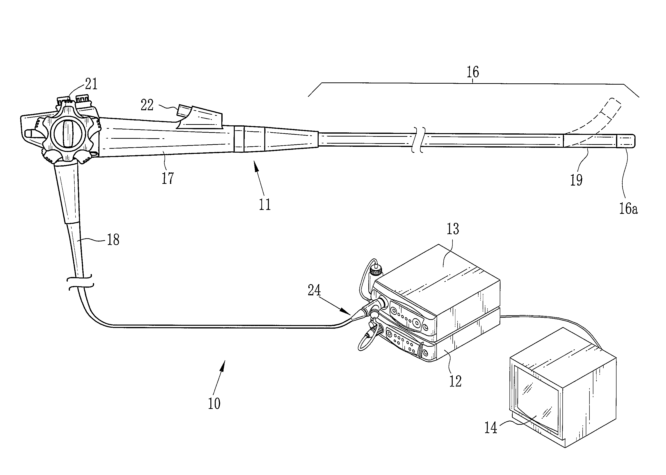
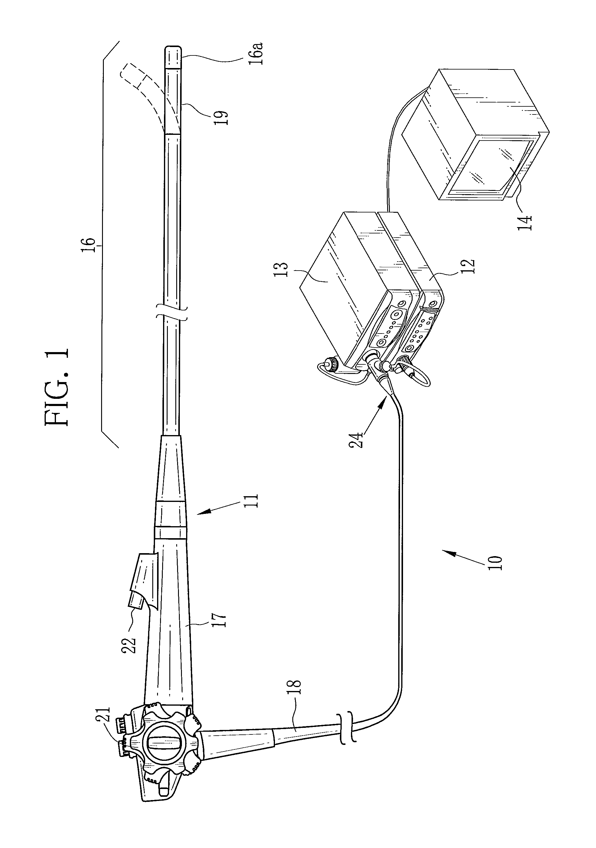
As shown in FIG. 1, an electronic endoscope system 10 of the present invention is provided with an electronic endoscope 11, a processing apparatus 12, a light source apparatus 13, and a monitor 14. The electronic endoscope 11 captures an image in a patient's body cavity. The processing apparatus 12 generates an image of a tissue site (an object of interest) in the body cavity based on a signal obtained by the image capture. The light source apparatus 13 supplies light for illuminating the body cavity. The monitor 14 displays the generated image. The electronic endoscope 11 is provided with a flexible insert section 16 to be inserted into the body cavity, a handling section 17 provided in the basal portion of the insert section 16, and a universal cord 18. The universal cord 18 connects the handling section 17, the processing apparatus 12, and the light source apparatus 13.

The insert section 16 has a bending portion 19 at its tip. The bending portion 19 has multiple joint pieces. Ope...


PUM


Abstract

An image of a tissue site including a blood vessel is captured while broadband light and narrow band light are emitted to a body cavity. Thereby, broadband image data corresponding to the broadband light and narrow band image data corresponding to the narrow band light are obtained. Picture elements in the same positions are identified between the broadband image and the narrow band image to obtain a brightness ratio LM therebetween. Based on depth correlation information between the brightness ratio and blood vessel depth, a blood vessel depth D corresponding to the brightness ratio is obtained to determine whether each picture element includes a blood vessel and whether the blood vessel depth D is at the surface. Based on the determination, a surface blood vessel region is extracted. A broadband image having the surface blood vessel region with the reduced contrast is generated.

Description

FIELD OF THE INVENTIONThe present invention relates to an electronic endoscope system for use in observation of a body cavity, a processing apparatus for an electronic endoscope, and a signal separation method.BACKGROUND OF THE INVENTIONRecently, diagnoses and medical treatments using electronic endoscopes are commonly performed in the medical field. An electronic endoscope has a long insert section to be inserted into a patient's body cavity. The electronic endoscope incorporates an imaging device such as a CCD at its distal end. The electronic endoscope is connected to a light source apparatus. The light source apparatus delivers light to the electronic endoscope via a light guide such as an optical fiber. The electronic endoscope emits the light from its distal end to illuminate the body cavity. The imaging device at the distal end of the insert section captures an image of a tissue site in the body cavity while the body cavity is illuminated. The image is subjected to various pr...

Claims


Application Information

Patent Timeline
Patent Type & Authority Applications(United States)
IPC IPC(8): A61B1/04
CPCA61B1/05A61B1/0638A61B1/0653A61B5/0071A61B5/0084A61B1/0669H04N5/2256H04N5/23203H04N5/2354A61B1/063A61B5/489A61B1/000094A61B1/0655H04N23/555H04N23/56H04N23/66H04N23/74
Inventor MINETOMA, YASUHIRO
Owner FUJIFILM CORP
Features
  • Generate Ideas
  • Intellectual Property
  • Life Sciences
  • Materials
  • Tech Scout
  • Unparalleled Data Quality
  • Higher Quality Content
  • 60% Fewer Hallucinations
Learn More