Portable ultrasound system

a portable ultrasound and diagnostic system technology, applied in the direction of diagnostics, machine supports, sustainable buildings, etc., can solve the problems of affecting the productive use of the system, hindering the ability of a person to productively use the system, and the hand of the system user that is not being used to manipulate the scan head is often occupied, so as to facilitate the carrying of the main unit and reduce the stress or work of the hand

Inactive Publication Date: 2011-05-12
ESAOTE EURO
View PDF23 Cites 36 Cited by
  • Summary
  • Abstract
  • Description
  • Claims
  • Application Information

AI Technical Summary

Benefits of technology

[0036]The elongated member forming the handle is oriented advantageously parallel to a peripheral edge of the display. This allows carrying the main unit easily in the correct orientation of the display for the user.
[0037]According to still another improvement, the case of the main unit can be carried easily either in a so called portrait or in a so called landscape orientation of the display, this means according to two orientations of the display which are rotated of 90° one with respect to the other around an axis of rotation that is perpendicular to the display and passes through the center of the display area.
[0041]This feature ensures that when the main unit is held in a position with the handle, i.e. the elongated member, in a vertical plane, the case is balanced and there is no major contribution of the weight in the part of the case protruding over the zone at which the hand grasps the elongated member.
[0042]In order to further facilitate the carrying of the main unit, reducing the stress or work of the hand to firmly block the case grasping the handle, and so enabling use of the hand for pressing the keys or buttons arranged on the elongated member, the invention provides, in one embodiment, for an ultrasound system with one or more of the features disclosed above and having also an attachment member for said main unit case, said attachment member being mountable around a forearm of the system user such that said display is visible to the system user during use.
[0058]The saddle like contact part can also be provided as unit formed by several parts which can be mounted one to the other when needed. In this case, for example, an additional case like element can be provided to be secured in an intermediate position between the saddle like contact part and the back side of the case of the main unit, while advantageously the additional case like element has, on one side to be connected to the backside of the case of the main unit, the same connection means as the side of the saddle like contact part, while on the side to be connected to the saddle like contact part it has the same connection means as the ones provided on the back side of the case of the main unit. This construction allows also providing more than one additional case like element, which can be secured one to the other and in an intermediate position between saddle like contact part and back side of the case of the main unit.

Problems solved by technology

The smaller and lighter equipment has improved portability, however, existing portable ultrasound technology is not without its limitations.
One shortcoming of some portable systems is that the need to hold onto or otherwise manipulate the equipment with both hands during use hinders the ability of a person to productively use the system in some situations.
As a result, the system user's hand that is not being used to manipulate the scan head is often nonetheless occupied and not always free to assist with the medical procedure.
While in essence permitting the scan head and the display to be held in one hand, these systems suffer from a different shortcoming.
In so doing, the displays of these systems may not be sufficiently visible to a user unless that user moves about, possibly into awkward positions.
These tasks must be carried out by the hand carrying the probe so that in certain situations the scanning process must be interrupted or even aborted due to the fact that some controls has to be activated on the main unit.
A general drawback of the increasing miniaturisation trend of the ultrasound systems consists in that said portable systems are limited of certain specific applications of the ultrasound imaging technique and that, in order to have systems able to carry put different kinds of applications of the ultrasound imaging technique, bigger and less portable devices are still needed.

Method used


Image

  • Portable ultrasound system
  • Portable ultrasound system
  • Portable ultrasound system

Examples


Embodiment Construction

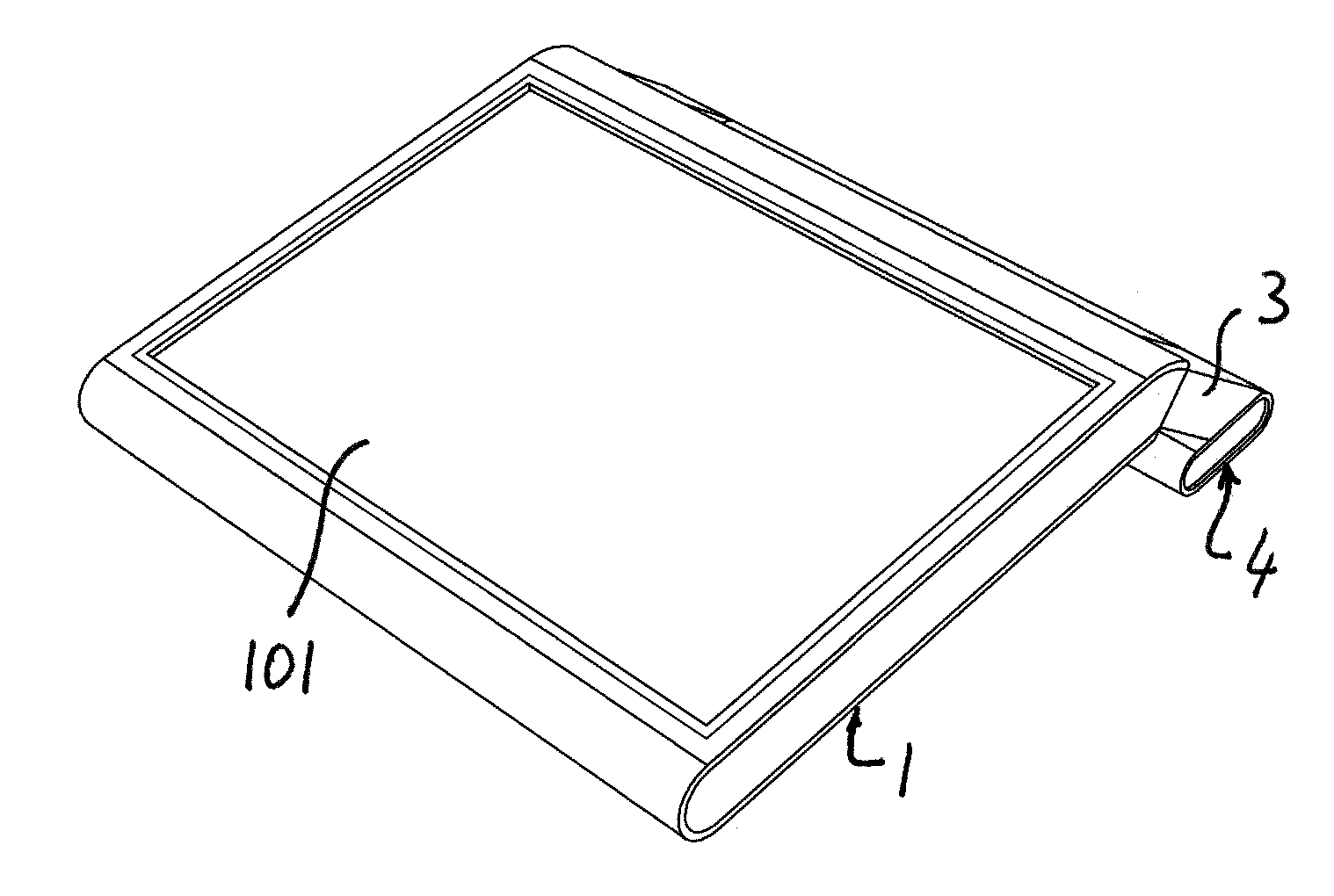
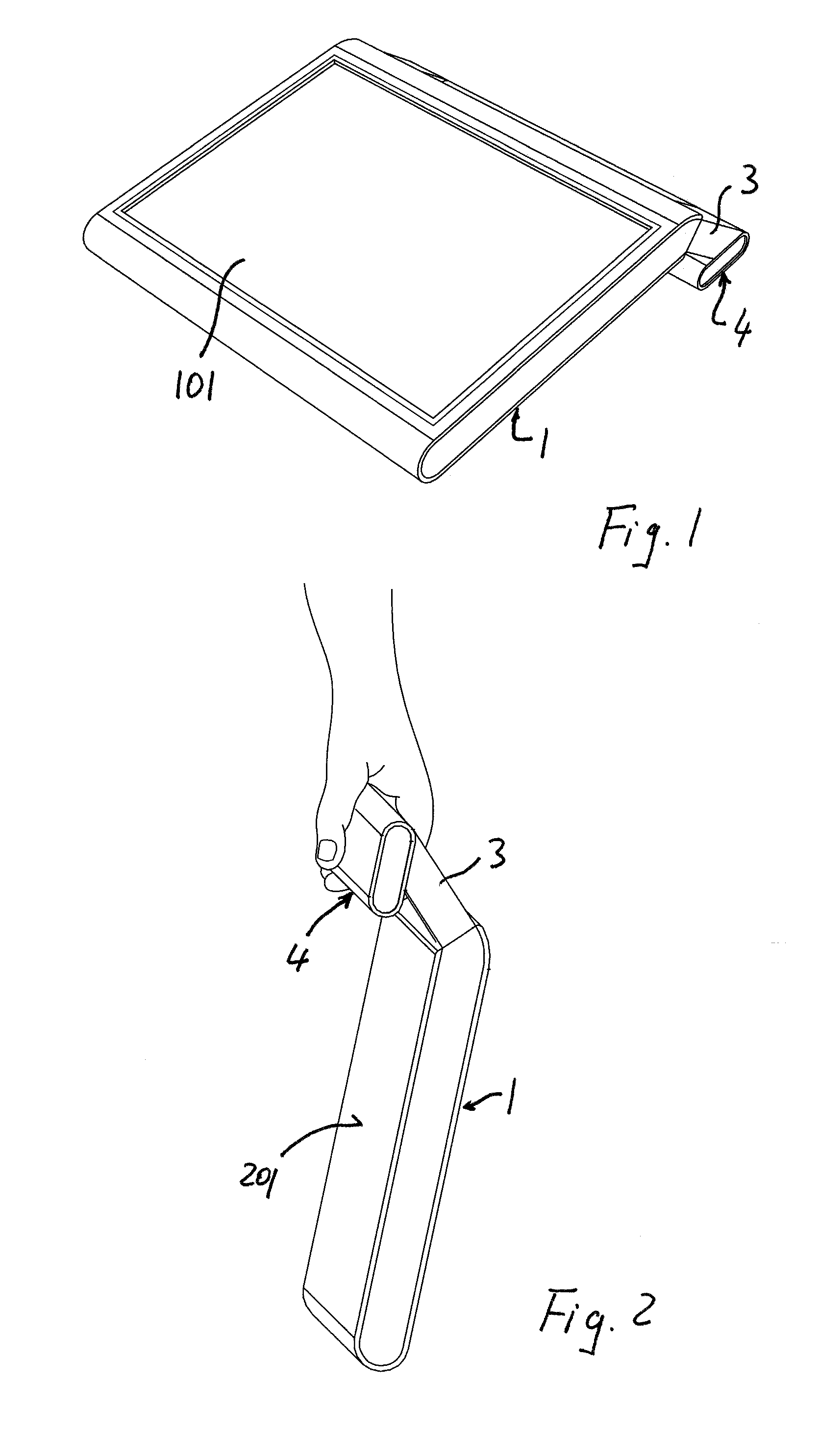
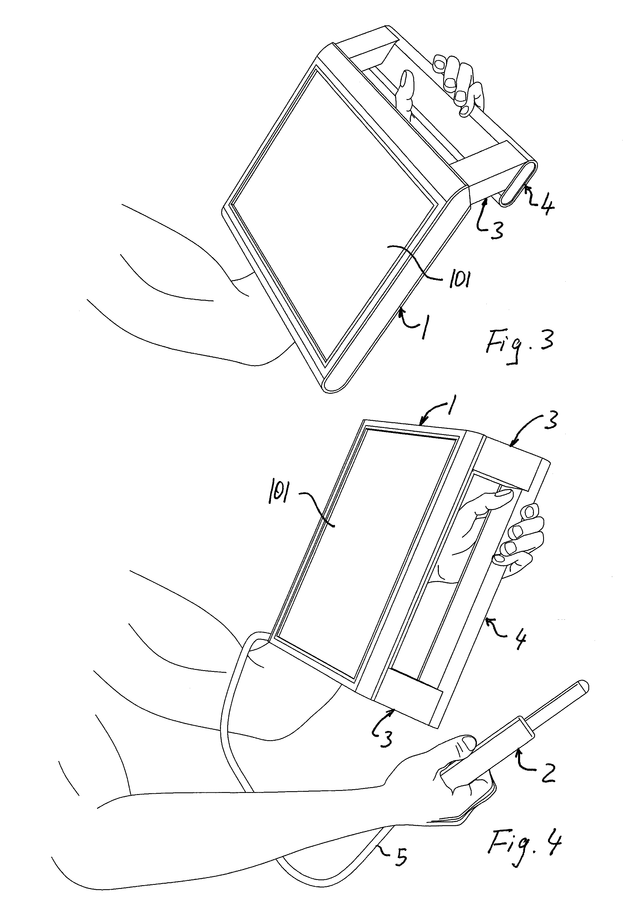
[0091]Referring to FIGS. 1 to 4, a portable ultrasound system comprises a main unit and a probe 2 which is connected to the main unit by means of a cable 5.

[0092]The probe 2 and the cable 5 can be connected to the main unit by means of usual connectors, which are not illustrated in detail since these connectors are known and widely used for connecting ultrasound probes.

[0093]The main unit comprises the hardware and software and the peripherals, which are necessary for driving the probe 2 to transmit ultrasound beams in a body under examination and to receive ultrasound beams from the body, and which are necessary for processing the received signals in order to generate diagnostic images of the inner parts of the body under examination.

[0094]The hardware of the main unit is housed in a case 1 which has the form of a so called portable tablet PC. In particular, the case is formed by a thin parallelepiped case having a front and a back side which are the largest sides. The front side i...


PUM


Abstract

A portable ultrasonic diagnostic system includes a probe transmitting and receiving an ultrasonic signal to and from a region of interest, and a main unit having circuitry in communication with the probe to form an image based on the ultrasonic signal and a display displaying the formed image. The main unit has a weight which can be supported by one arm and is provided with handle means to be grasped by one hand. The main unit has a case in the form of a tablet computer, with a front side formed by a display and a rear side, and further has a handle.

Description

FIELD OF THE INVENTION[0001]The invention relates to portable ultrasonic diagnostic systems, and, in particular, to a portable ultrasound diagnostic system that includes:[0002]a probe for transmitting and receiving an ultrasonic signal to and from a region of interest;[0003]a main unit having circuitry in communication with the probe for forming an image of the region of interest based on the ultrasonic signal and;[0004]a display for displaying the formed image;[0005]the probe being connected to the said circuitry in the main unit by means of a cable connection;[0006]the main unit having a weight which can be supported by one arm, and;[0007]the main unit being provided with handle means to be grasped by one hand.BACKGROUND OF THE INVENTION[0008]Ultrasonic systems or devices of the diagnostic kind are known and are the result of advances in the underlying technology, which have permitted miniaturization of the necessary electronics. The ultrasound industry continues to reduce the siz...

Claims


Application Information

Patent Timeline
Patent Type & Authority Applications(United States)
IPC IPC(8): A61B8/00
CPCA61B8/00Y02B60/144A61B8/467A61B2560/0209A61B2560/0431F16M13/00G01S7/52079G01S7/52084G06F1/1626G06F1/1632G06F1/1656G06F1/3203G06F1/329G06F1/3293G06F2200/1614Y02B60/121A61B8/462A61B8/469F16M11/041F16M11/10F16M11/105F16M11/2021F16M11/38F16M13/04F16M2200/08A61B8/4427A61B8/4433Y02D10/00
Inventor WILLEMS, JOHNGEIJSEN, JOOP
Owner ESAOTE EURO
Why Eureka
Try Eureka