
Class Resonant-H Electrosurgical Generators

a generator and resonant-h technology, applied in the direction of pulse generator, push-pull amplifier, pulse generator, etc., can solve the problems of heat and destruction surrounding issues, inefficiency of commonly used power amplifiers, and heat becomes difficult to manag

Active Publication Date: 2011-05-19
TYCO HEALTHCARE GRP LP
View PDF13 Cites 56 Cited by
  • Summary
  • Abstract
  • Description
  • Claims
  • Application Information

AI Technical Summary

Benefits of technology

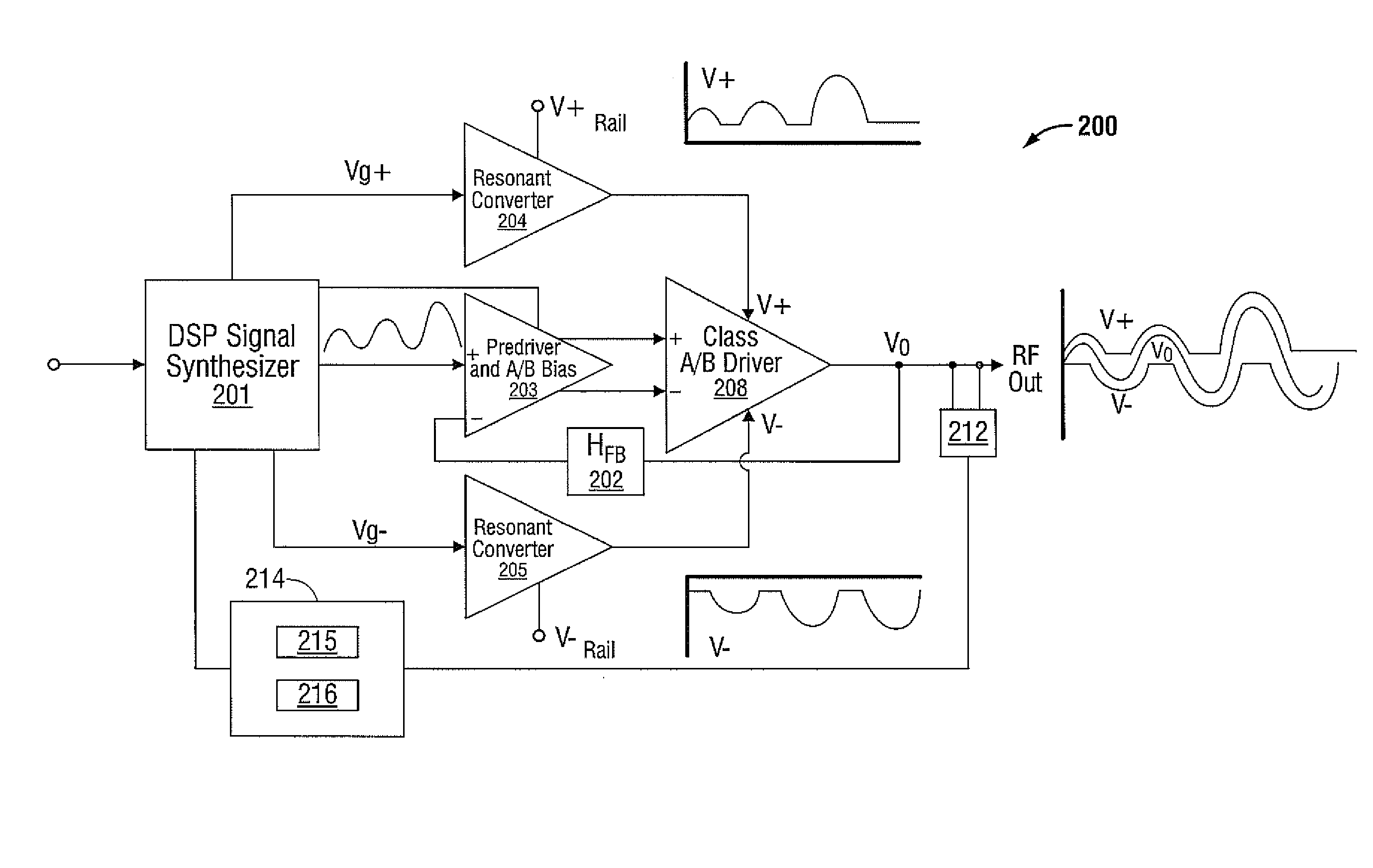
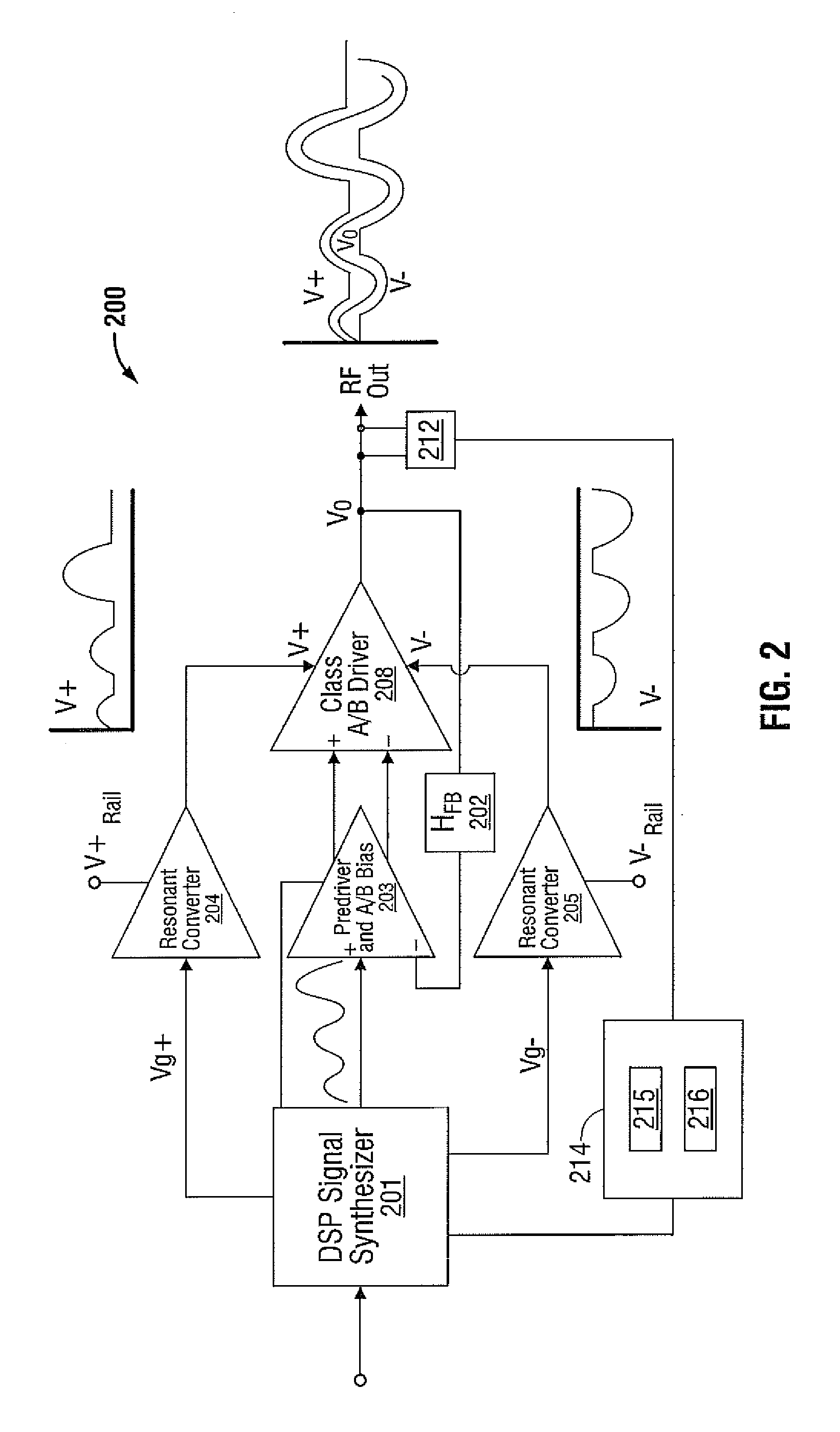
[0011]In another embodiment, an electrosurgical generator is provided having a voltage source, a gain stage, a class resonant-H amplifier, at least one switch, and a controller operable to control an output of the voltage source and control the at least one switch based o

Problems solved by technology

Typically, the current density is very high near the tip of the needle electrode, which tends to heat and destroy surrounding issue.
Commonly used power amplifiers are known to be inefficient.
The resulting heat becomes difficult to manage and may require the use of bulky and costly cooling systems, e.g., fans and heat sinks.
Additionally, the excess heat may cause thermal stress to other components of the generator, shortening generator life, decreasing reliability, and increasing maintenance costs.
Additionally, a class A / B amplifier may exhibit crossover distortion that introduces undesirable harmonics into the surgical signal, which are known to cause radiofrequency interference in excess of acceptable
However, such an arrangement has a disadvantage in that the quality factor or Q factor changes with the load applied to the circuit making it difficult to maintain the desired voltage or current at the output.
A manifestation of this disadvantage may be excessive or undesired “ringing” at the output for underdamped or high Q situations of loading.

Method used


Image

  • Class Resonant-H Electrosurgical Generators
  • Class Resonant-H Electrosurgical Generators
  • Class Resonant-H Electrosurgical Generators

Examples


Embodiment Construction

[0021]Particular embodiments of the present disclosure are described hereinbelow with reference to the accompanying drawings; however, it is to be understood that the disclosed embodiments are merely exemplary of the disclosure, which may be embodied in various forms. Well-known functions or constructions are not described in detail to avoid obscuring the present disclosure in unnecessary detail. Therefore, specific structural and functional details disclosed herein are not to be interpreted as limiting, but merely as a basis for the claims and as a representative basis for teaching one skilled in the art to variously employ the present disclosure in virtually any appropriately detailed structure.

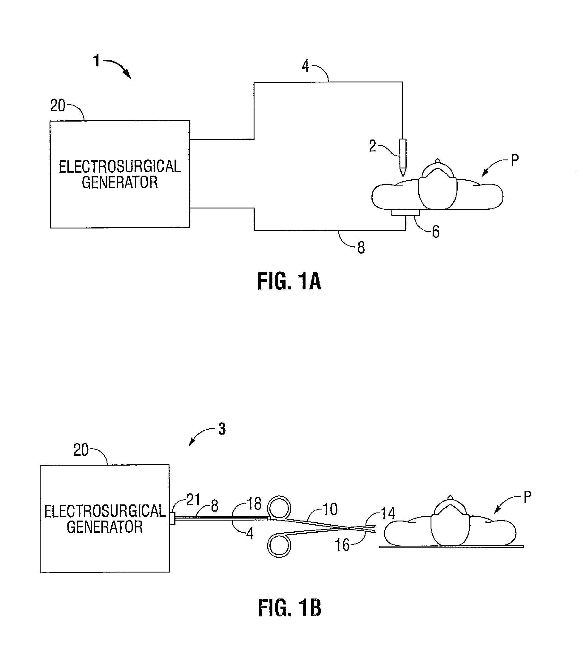
[0022]The generator according to the present disclosure can perform ablation, monopolar and bipolar electrosurgical procedures, including vessel sealing procedures. The generator may include a plurality of outputs for interfacing with various electrosurgical instruments (e.g., a monopolar a...


PUM


Abstract

A generator for use with an electrosurgical device is provided. The generator has a gain stage electrically disposed between a first voltage rail and a second voltage rail, wherein the gain stage includes an input and an output. A voltage source operably coupled to the gain stage input and configured to provide an input signal thereto responsive to a drive control signal is also provided. The generator also has one or more sensors configured to sense an operational parameter of the amplifier and to provide a sensor signal corresponding thereto and a controller adapted to receive the sensor signal(s) and in response thereto provide a drive control signal to the voltage source. The generator has an amplifier output configured to supply an output voltage corresponding to the first voltage rail and the second voltage rail when the output of the gain stage falls between a voltage of the first voltage rail and a voltage of the second voltage rail and is configured to supply a peak voltage output when the voltage output is falls greater than the voltage of the first voltage rail or less than the voltage of the second voltage rail.

Description

BACKGROUND[0001]1. Technical Field[0002]The present disclosure relates to systems for providing energy to biological tissue and, more particularly, to improved apparatus for amplifying energy for use during electrosurgical procedures.[0003]2. Background of Related Art[0004]Energy-based tissue treatment is well known in the art. Various types of energy (e.g., electrical, ultrasonic, microwave, cryogenic, thermal, laser, etc.) are applied to tissue to achieve a desired result. Electrosurgery involves application of high radio frequency electrical current to a surgical site to cut, ablate, coagulate or seal tissue. In monopolar electrosurgery, a source or active electrode delivers radio frequency energy from the electrosurgical generator to the tissue and a return electrode carries the current back to the generator. In monopolar electrosurgery, the source electrode is typically part of the surgical instrument held by the surgeon and applied to the tissue to be treated. A patient return...

Claims


Application Information

Patent Timeline
IPC IPC(8): H03F3/26H03G3/10H03B1/00
CPCA61B18/1206A61B2018/00767A61B2018/00892H03F1/0238H03F3/2178H03F3/45475H03K5/01H03F3/45071H03F2200/138H03F3/2171
Inventor GILBERT, JAMES A.
Owner TYCO HEALTHCARE GRP LP
Learn More