Power conversion equipment

a technology of power conversion equipment and inverter, which is applied in the direction of power conversion systems, electrical apparatus, ac-dc conversion, etc., can solve the problems of increasing the cost of equipment, increasing the size of equipment, and increasing the power factor, so as to reduce the cost of equipment

Inactive Publication Date: 2011-05-19
FUJI ELECTRIC CO LTD
View PDF3 Cites 49 Cited by
  • Summary
  • Abstract
  • Description
  • Claims
  • Application Information

AI Technical Summary

Benefits of technology

[0014]According to the invention, in a power conversion equipment (or device) that can output an alternating current voltage having three or more different potentials in a half-cycle, it is possible to achieve t

Problems solved by technology

However, in the event that the voltages of the positive electrode side and negative electrode side capacitors of the three-level inverter become unbalanced, the power factor worsens.
However, due to variations in IGBT operation and control, part variation, and the like, it is difficult to avert voltage unbalance with only the heretofore described circuit co

Method used


Image

  • Power conversion equipment
  • Power conversion equipment
  • Power conversion equipment

Examples


first embodiment

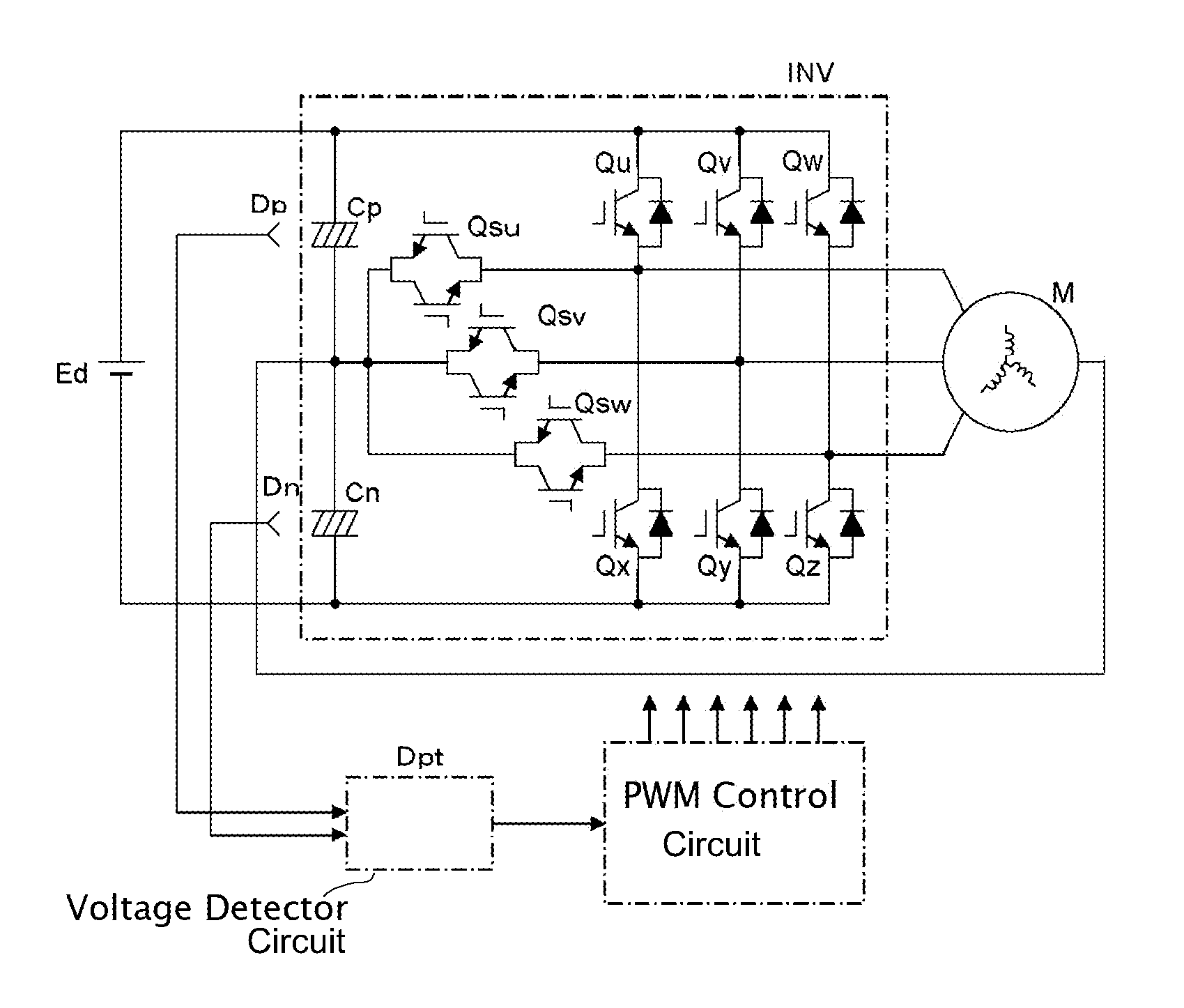
[0026]FIG. 1 shows a first embodiment of the invention. The embodiment is a power conversion equipment (a three-level inverter) that can output an alternating current voltage having three or more different potentials in a half-cycle period using IGBTs as semiconductor switching elements. A direct current circuit portion of the three-level inverter has a configuration wherein it has a series circuit of capacitors Cp and Cn between a positive electrode and a negative electrode as a direct current input, and a direct current power supply Ed is connected in parallel to the series circuit.

[0027]Also, an inverter INV has a configuration wherein each of bidirectional switches Qsu, Qsv, and Qsw, wherein reverse blocking type IGBTs are inverse parallel connected, is connected between alternating current terminals of a bridge circuit configured of six IGBTs (Qu, Qv, Qw, Qx, Qy, and Qz) and an internal connection point of the capacitor series circuit. Also, a connection point of the capacitor ...

second embodiment

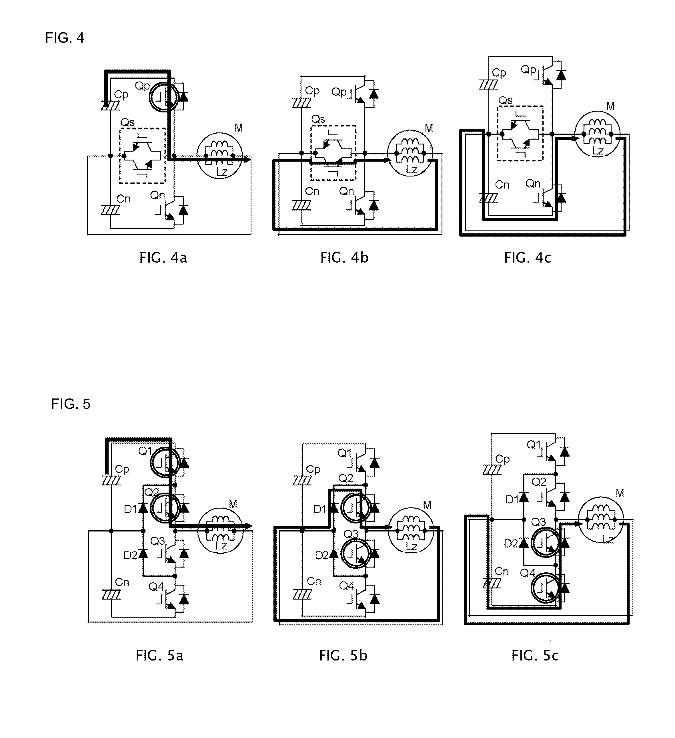
[0035]FIGS. 5A to 5C show a second embodiment of the invention. FIGS. 5A to 5C show a circuit configuration in a common neutral point clamping type three-level inverter using a clamping diode. Hereafter, operations will be described.

[0036]FIG. 5A showing a mode wherein IGBTs Q1 and Q2 are turned on, and the alternating current load M is supplied from the positive side electrode capacitor Cp, energy is accumulated in the inductor Lz. Next, on the IGBT Q1 being turned off, and an IGBT Q3 turned on, the energy accumulated in the inductor Lz flows back via the IGBT Q2, as shown in FIG. 5B. Next, on the IGBT Q2 being turned off, and an IGBT Q4 turned on, the energy accumulated in the alternating current load is accumulated in the negative electrode side capacitor Cn via a diode inverse parallel connected to the IGBTs Q3 and Q4. Also, as a transfer of energy from the negative electrode side capacitor Cn to the positive electrode side capacitor Cp is also an inversely symmetrical operation...

third embodiment

[0038]FIG. 6 shows a third embodiment of the invention. It is an equivalent circuit focused on a zero phase sequence component showing an embodiment in a five-level inverter. A five-level inverter is a power conversion circuit that outputs an alternating current voltage having five potentials in a half-cycle period. A configuration is such that the two capacitors Cp and Cn of the direct current input of the inverter INV of the first embodiment shown in FIG. 1 are changed to four capacitors Cp1, Cp2, Cn1, and Cn2, and bidirectional switches are connected between connection points of the capacitors and alternating current outputs of the inverter. A neutral point of a load and an intermediate connection point of the series capacitor are connected.

[0039]Operations in this kind of configuration are similar to those in the first embodiment.

[0040]In a mode in which the IGBT Qp is turned on and off, on the IGBT Qp being turned on, the series circuit of the capacitors Cp1 and Cp2 is a power ...


PUM


Abstract

In a power conversion device, a capacitor series circuit is connected in parallel with a direct current power supply, outputs an alternating current voltage having three or more potentials in a half-cycle period with the capacitor series circuit as a direct current input, wherein a neutral point of an alternating current load and an intermediate connection point of the capacitor series circuit are directly connected, the voltage of each of the capacitors is detected, and a zero voltage vector obtained by making each alternating current output of the same potential is adjusted in accordance with the difference between the voltages.

Description

BACKGROUND OF THE INVENTION[0001]1. Technical Field[0002]The present invention relates to a multilevel inverter that outputs an alternating current voltage having three or more different potentials in a half-cycle period, and in particular, relates to a technology for balancing the voltage of each capacitor in a capacitor series circuit installed in a direct current input.[0003]2. Related Art[0004]FIG. 7 shows a circuit of a power conversion equipment (a three-level inverter) that outputs an alternating current voltage having three or more different potentials in a half-cycle period using IGBTs as semiconductor switching elements. Although there are also configurations having more than three levels, such as five levels, as a multilevel inverter, a description will be given here with a three-level inverter as an example. A direct current circuit portion of the three-level inverter has a configuration wherein it has a series circuit of capacitors Cp and Cn on a positive electrode side...

Claims


Application Information

Patent Timeline
IPC IPC(8): H02M7/5387
CPCH02M7/487H02M7/53876
Inventor TABATA, MASAFUMIFUJITA, KOUETSU
Owner FUJI ELECTRIC CO LTD
Why Eureka
Try Eureka