Eye-safe laser-based lighting

a laser-based lighting and laser-based technology, applied in the field of laser-based light sources, can solve the problems of annoying speckles, low illumination efficiency of laser-based light, etc., and achieve the effect of reliable eye safety

Inactive Publication Date: 2011-05-19
KONINKLIJKE PHILIPS ELECTRONICS NV
View PDF24 Cites 50 Cited by
  • Summary
  • Abstract
  • Description
  • Claims
  • Application Information

AI Technical Summary

Benefits of technology

[0007]It is an object of the invention to provide a laser-based light source and a method of operating the same, which enable reliable eye-safety to be achieved in an easy way.
[0014]The invention is applicable for different types of light-conversion devices. Especially, as light-conversion devices, phosphors as described above, but also up-conversion materials, are preferred, i.e. devices which convert the light to light of another wavelength. But also materials that do not alter the wavelength but the beam properties, e.g. scattering devices, are preferred. Especially the use of a scattering device is advantageous, since this allows reducing the coherence of the beam and, thus, reduces speckle.
[0016]In general, different types of sensors can be used as laser-output sensor or converted-light sensor. However, according to a preferred embodiment of the invention, the laser-output sensor is formed by a laser-light photodiode adapted for receiving at least a part of the laser light. With respect to this, it is preferred to use a beam splitter in order to direct a part of the laser light emitted by the laser device to the laser-light photodiode. In this way, a direct measurement of the laser output can be achieved. Additionally or alternatively, the laser-output sensor is preferably formed by a laser driving current monitor adapted for monitoring the laser driving current. With respect to this, it is especially preferred to monitor the laser driving current, which is typically proportional to a laser output, apart from a threshold current.
[0021]Finally, it should be emphasized that according to a preferred embodiment of the invention, the light source is enclosed to prevent tampering and to preclude as much as possible that external straylight, e.g. daylight or artificial light, enters and influences the output signals of the laser-output sensor and the converted-light sensor.
[0032]Further, it is preferred that the method comprises the step of determining the safe-to-operate parameter, based on a ratio between the laser-output signal and the converted-light signal. Furthermore, it is preferred that the step of determining the safe-to-operate parameter is based on the derivative with respect to time of the ratio between the laser-output signal and the converted-light signal. With these ratios it can be ascertained in an easy and reliable way whether the light source is safe to operate.
[0034]According to another preferred embodiment of the invention, the step of controlling the operation of the laser-based light source, based on the comparison of the safe-to-operate parameter with the predefined threshold, comprises shutting down laser emission or / and generating a warning. In this way, a user of the light source is at least warned that handling the damaged light source might be dangerous, and if laser emission is shut down, there is no longer a risk of eye-injury due to the laser beam.

Problems solved by technology

Laser light by itself will not be of much use for illumination since the laser beam is too bright to be eye-safe, too monochromatic for faithful colour reproduction and will result in annoying speckle due to its coherence.
However, one critical issue with laser-based lighting is the fact that the light source should adhere to strict legislation and be eye-safe under all circumstances, even when tampered with.

Method used


Image

  • Eye-safe laser-based lighting
  • Eye-safe laser-based lighting
  • Eye-safe laser-based lighting

Examples


Embodiment Construction

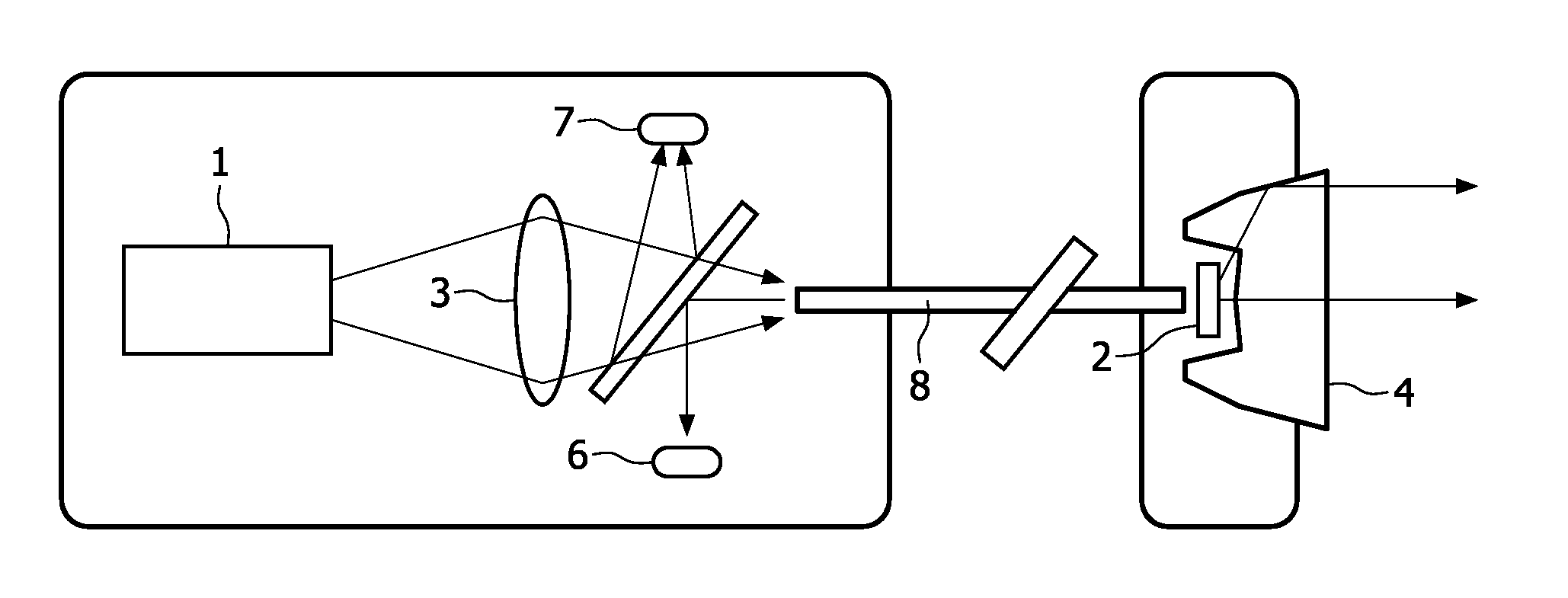
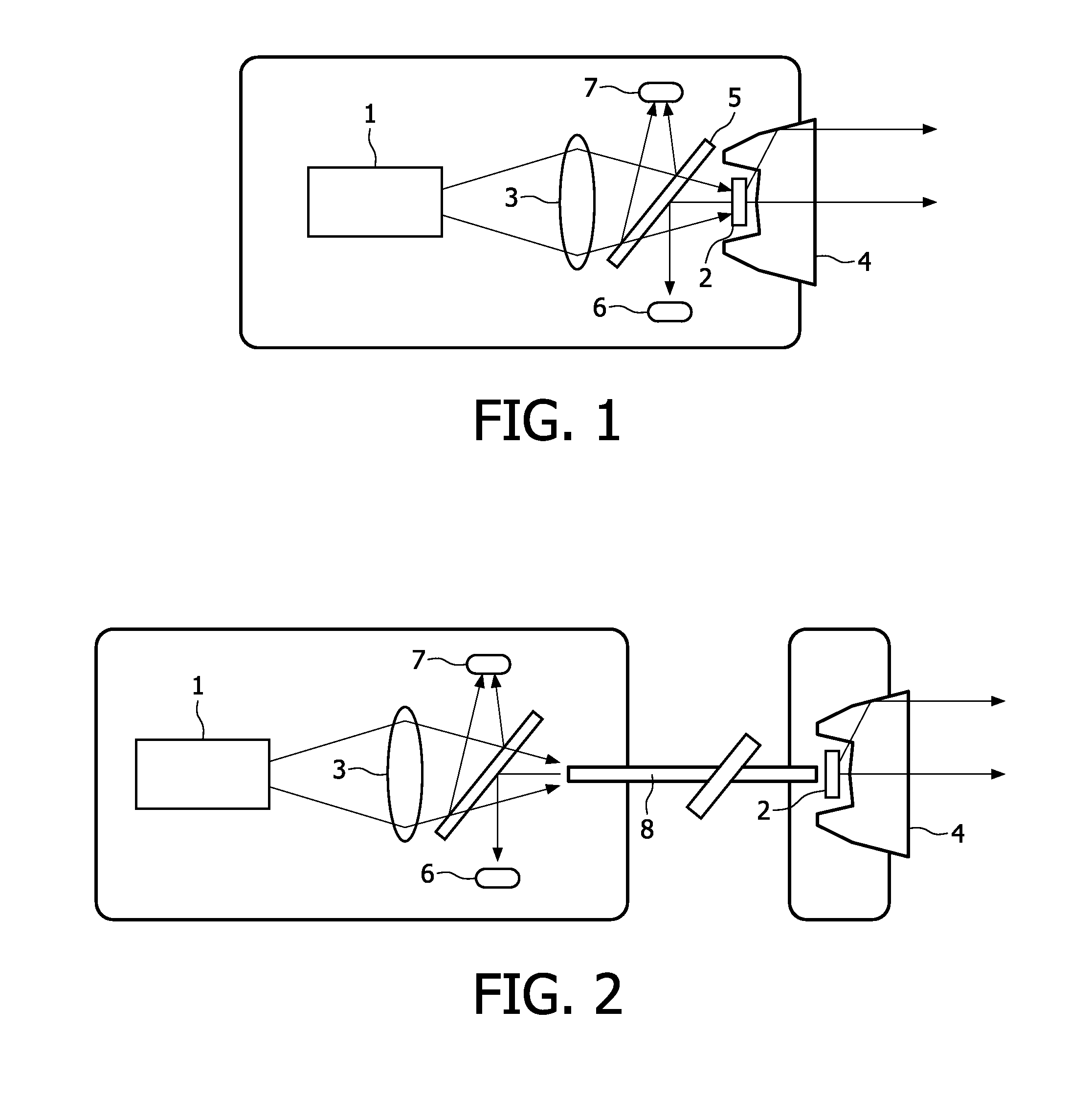
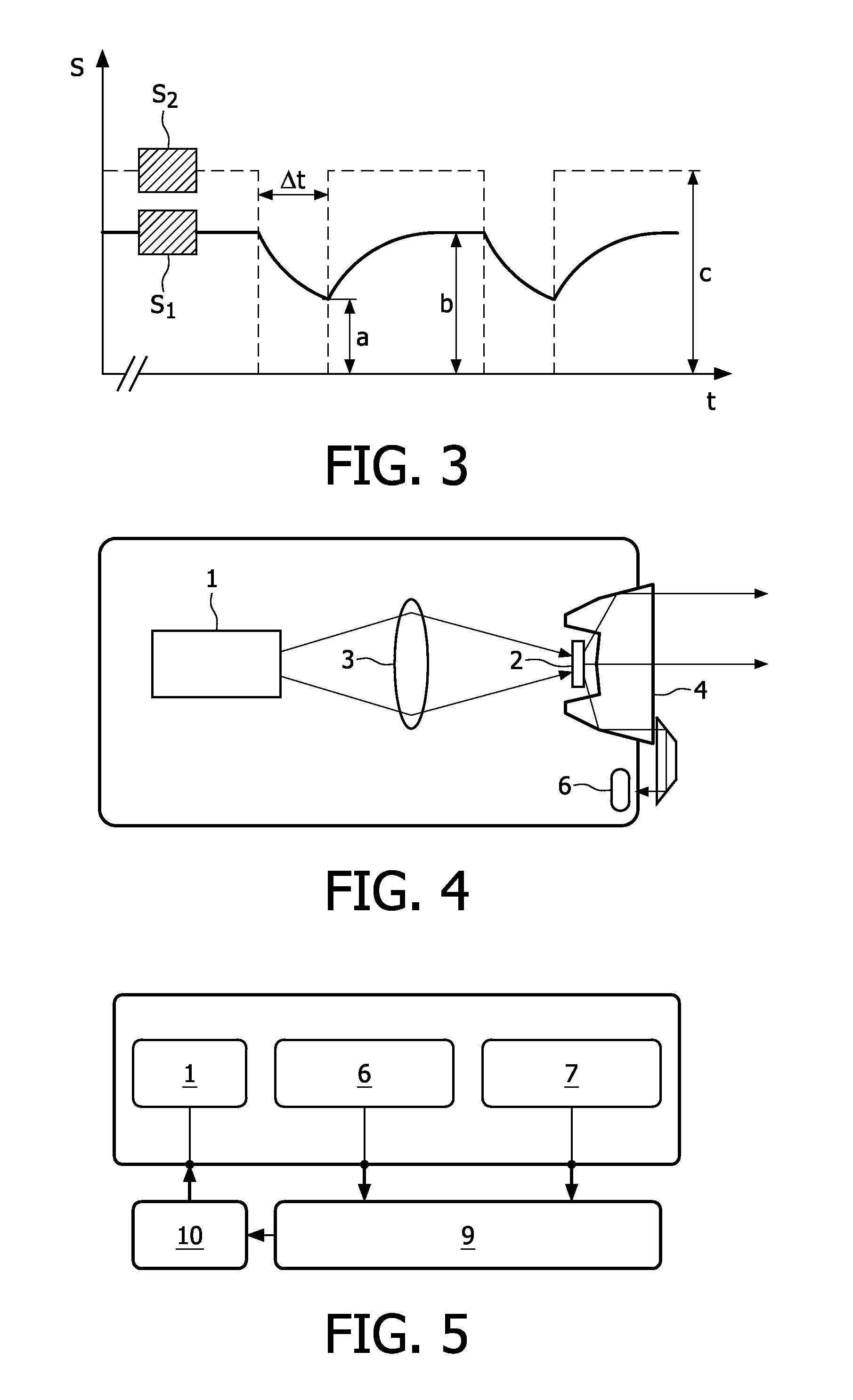
[0044]A first embodiment according to the invention is schematically depicted in FIG. 1. Laser light is generated by a laser device 1, i.e. a diode laser, e.g. in an edge-emitting geometry or a vertical-cavity surface-emitting geometry (VCSEL). This laser light is directed via optics 3 to a volume of phosphorous material of a light-conversion device 2 which is in a powderous or crystalline, preferably polycrystalline, state. The laser device 1 emits blue light, preferably around 445 nm. The light-conversion device 2 converts the blue laser light into broadband yellow light. The combination of this yellow light and the remainder of the blue light results in white light. The white light generated in this way is shaped into a beam by means of collimating optics 4.

[0045]Some of the light generated by the light-conversion device 2 as well as some of the laser light is redirected towards the laser device 1. A beam splitter 5 at an angle of 45° is used to direct a fraction of this light to...


PUM


Abstract

The invention relates to a laser-based light source comprising a laser device (1) adapted for generating laser light of a predetermined laser wavelength and emitting this laser light as a laser beam; a light-conversion device (2) for converting at least part of the laser light into converted light; a laser-output sensor (7) for determining a laser-output signal proportional to the output of laser light emitted by the laser device (1); a converted-light sensor (6) for determining a converted-light signal proportional to the output of converted light emitted by the light-conversion device (7); and a controller (9) which is adapted for receiving the laser-output signal and the converted-light signal, for determining a safe-to-operate parameter, based on the laser-output signal and the converted-light signal, and for controlling the operation of the laser-based light source, based on a comparison of the safe-to-operate parameter with a at least one predefined threshold. In this way, a laser-based light source is proposed which enables reliable eye-safety in an easy way.

Description

FIELD OF THE INVENTION[0001]The invention relates to the field of a laser-based light source and a method of operating the same, and especially to eye-safe laser-based lighting.BACKGROUND OF THE INVENTION[0002]During the last decades, thanks to the advances of semiconductor technology, LEDs (Light Emitting Diodes) have become more and more important in lighting applications. Technological breakthroughs in high-power LEDs have opened the door to new lighting concepts driven by miniaturization, lifetime, efficiency and sustainability.[0003]Compared to LEDs, the advantage of lasers is their much higher brightness. Semiconductor lasers have started to become available in output powers of several Watts, thus enabling a high lumen output. Laser light by itself will not be of much use for illumination since the laser beam is too bright to be eye-safe, too monochromatic for faithful colour reproduction and will result in annoying speckle due to its coherence. A convenient way to resolve the...

Claims


Application Information

Patent Timeline
Patent Type & Authority Applications(United States)
IPC IPC(8): H01S3/13
CPCF21K9/00H01S5/005H01S5/06808F21V25/00H01S5/0683F21K9/56F21V23/0457H01S5/06825F21K9/64F21V25/02F21Y2115/30F21S41/16F21S45/70H01S5/0087H01S5/0078
Inventor KRIJN, MARCELLINUS PETRUS CAROLUS MICHAELJAK, MARTIN JACOBUS JOHAN
Owner KONINKLIJKE PHILIPS ELECTRONICS NV
Why Eureka
Try Eureka