Optimization of RF transmit and gradient magnetic field imaging using radio frequency and gradient coils

a magnetic field and gradient technology, applied in the field of magnetic resonance imaging techniques and devices, can solve the problems of physiological limitations preventing one from crossing certain thresholds of gradient and rf field parameters, physiological limitations are typically the amount of heat deposited in the patient, physiological limitations are typically the induced peripheral nerve stimulation (pns), etc., to achieve the effect of increasing the peak b1 transmit field amplitude, improving mr image quality, and increasing the gradient magnetic field

Inactive Publication Date: 2011-05-19
GENERAL ELECTRIC CO
View PDF8 Cites 25 Cited by
  • Summary
  • Abstract
  • Description
  • Claims
  • Application Information

AI Technical Summary

Benefits of technology

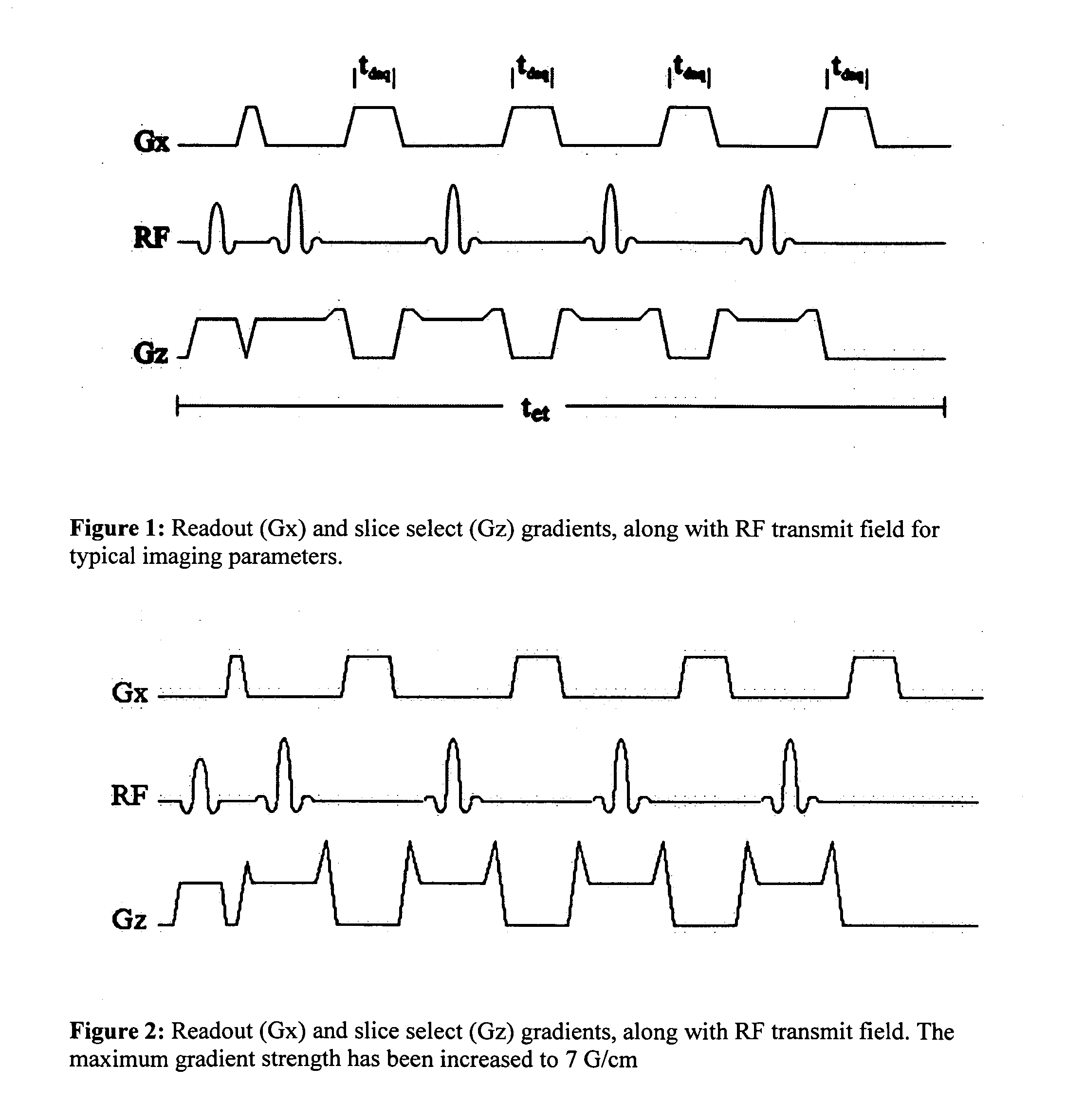
[0050]The disclosed embodiments further provide a method for improving MR image quality, including increasing the peak B1 transmit field amplitude, increasing the gradient magnetic field and reducing the duration of the transmit pulse simultaneously.
[0051]In further accordance with the disclosed embodiments, the duration of the transmit pulse may be reduced to provide additional time during a pulse sequence to receive signal from a region of interest. The duration of the transmit pulse may be reduced to compress the echo train in order to acquire image data at a relatively faster ...

Problems solved by technology

There are several important fundamental limitations that restrict the push to faster, stronger gradient fields and stronger RF fields.
In addition to the numerous technical challenges, there are physiological limitations preventing one from crossing certain thresholds of gradient and RF field parameters.
For RF transmit coils, depending on the imaging sequence parameters, the physiological limitation is typically the amount of heat deposited in the patient, on both a local level and a whole body level.
For gradient fields, the physiological limitation is typically the induced Peripheral Nerve Stimulation (PNS).
At even higher levels it could lead ...

Method used


Image

  • Optimization of RF transmit and gradient magnetic field imaging using radio frequency and gradient coils
  • Optimization of RF transmit and gradient magnetic field imaging using radio frequency and gradient coils
  • Optimization of RF transmit and gradient magnetic field imaging using radio frequency and gradient coils

Examples


Embodiment Construction

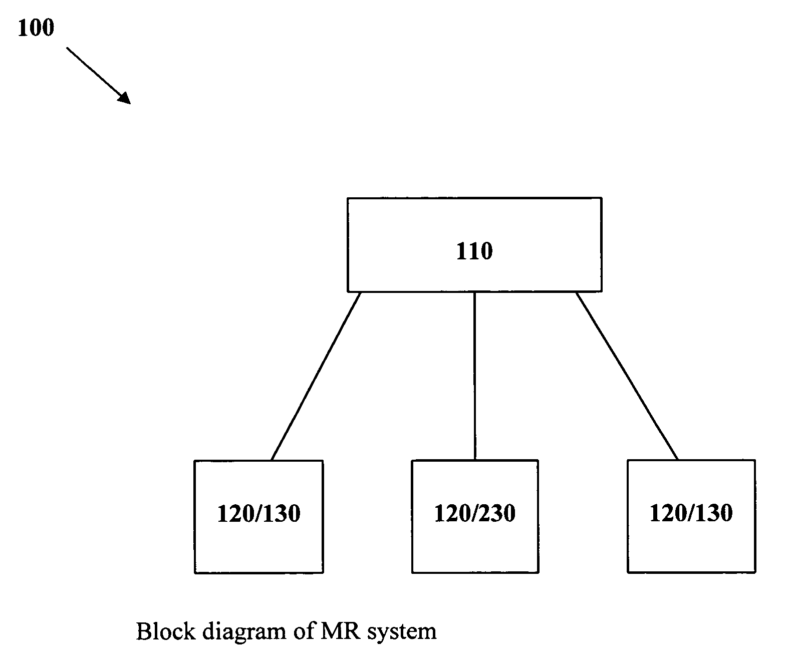
[0075]Reference will now be made in detail to the present preferred embodiments of the invention, examples of which are illustrated in the accompanying drawings. The method and corresponding steps of the invention will be described in conjunction with the detailed description of the system.

[0076]Embodiments of the subject invention relate to the use of smaller gradient and RF coils, and dynamically adjusting the gradient and RF pulse sequences in a way that depends upon the anatomy being imaged and the hardware being used during the exam, preferably for imaging only a portion of the body for purposes of enhancing imaging performance. The methods improve upon whole body systems by operating the coils at RF and gradient field strengths that would otherwise create unacceptably excessive heating or Peripheral Nerve Stimulation (PNS).

[0077]In accordance with one embodiment, the smaller geometry of the anatomy being imaged (and the scanner) leads to lower exposure to electromagnetic field...


PUM


Abstract

The invention provides various systems, machine readable programs and methods for performing imaging using a MR scanner. The MR scanner includes at least one local radio-frequency transmit coil and at least one local gradient coil. The local radio-frequency transmit coil(s) and local gradient coil(s) cooperate to define an imaging volume. The MR scanner further includes a control system for performing an imaging operation on a patient's anatomy disposed within the imaging volume. The control system permits a selective simultaneous increase of the gradient magnetic field strength and peak B1 field strength by substantially the same factor, f.

Description

CROSS-REFERENCE TO RELATED APPLICATIONS[0001]The present patent application claims the benefit of priority to U.S. Patent Application Ser. No. 61 / 033,467 filed Mar. 4, 2008, which is incorporated by reference herein in its entirety.BACKGROUND OF THE INVENTION[0002]1. Field of the Invention[0003]The present invention relates to improved techniques and devices for performing magnetic resonance imaging (“MRI”).[0004]2. Description of Related Art[0005]The vast majority of MRI systems available today are general-purpose whole body systems with built in RF body transmit and body gradient coils. There is another more limited class of dedicated extremity systems [1,2] where the main focus has been lower cost of the system and making it easier to locate.[0006]Relative to whole body systems the trend toward higher performance solutions centers around (1) increasing the field strength for higher signal-to-noise, (2) making arrays of a large number of relatively smaller receive only RF coils [3...

Claims


Application Information

Patent Timeline
IPC IPC(8): A61B5/055
CPCG01R33/022A61B5/055
Inventor ROEMER, PETER B.MALLOZZI, RICHARD P.CHENG, YUAN
Owner GENERAL ELECTRIC CO
Why Eureka
Try Eureka