
Oil free falling film heat exchanger

a heat exchanger and film heat exchange technology, applied in the direction of heat exchange apparatus, trickle coolers, stationary conduit assemblies, etc., can solve the problems of inefficient use of air as a secondary fluid, limited heat carrying capacity of air, and substantial frictional losses over such a distance, so as to reduce gas charges and heat exchange rates , the effect of increasing the effective surface area

Inactive Publication Date: 2011-05-26
RINGWALDT SAMUEL ALEXANDER
View PDF12 Cites 22 Cited by
  • Summary
  • Abstract
  • Description
  • Claims
  • Application Information

AI Technical Summary

Benefits of technology

[0020]The use of the falling film to wet the primary surface of the plates—as opposed to immersing the plates in a mass of boiling refrigerant—substantially reduces the gas charge required.

Problems solved by technology

However, when considering larger structures, the use of air as a secondary fluid becomes inefficient.
The frictional losses using air over such a distance are substantial.
Further, the heat carrying capacity of air is limited by its relatively low density.
Although the flooded type produces very efficient heat transfer, it does have drawbacks.
The main drawback is the excessive amount of liquid refrigerant required to completely submerge the copper tubes (an excessive “gas charge”).
The HVAC industry is now under pressure to reduce the gas charge in systems owing to expense and the potential for environmental contamination.
The tendency of the liquid refrigerant to collect in the bottom of the shell means that the oil circulating in the system also tends to become trapped there.
This can cause continual oil shortage problems at the compressor unless special oil recovery devices are added to the design of the heat exchanger.
The entrapped oil decreases the efficiency of the heat exchanger and—of course—potentially starves the compressor of lubrication.
One of the main causes of compressor failure in refrigeration systems is inadequate oil return.
Such heat exchangers are not very space efficient.
Global warming and other environmental concerns disfavor the use of large gas charges.

Method used


Image

  • Oil free falling film heat exchanger
  • Oil free falling film heat exchanger
  • Oil free falling film heat exchanger

Examples


Embodiment Construction

[0113]A plate-type heat exchanger transfers heat from a secondary fluid to a primary fluid across a plate which separates the two. It is preferable to completely cover the primary fluid side of the plate with refrigerant. As discussed previously, this can be done in two ways. The first way is to flood the primary side of the plate with a “bath” of boiling refrigerant. The second way is to apply a thin “falling film” of refrigerant to the primary fluid side. The two methods can be practiced using many of the same heat exchanger components. However, they will be discussed in separate sections in order to prevent confusion. The flooded type is discussed first and the falling film type is discussed second.

1. Flooded Type Heat Exchanger

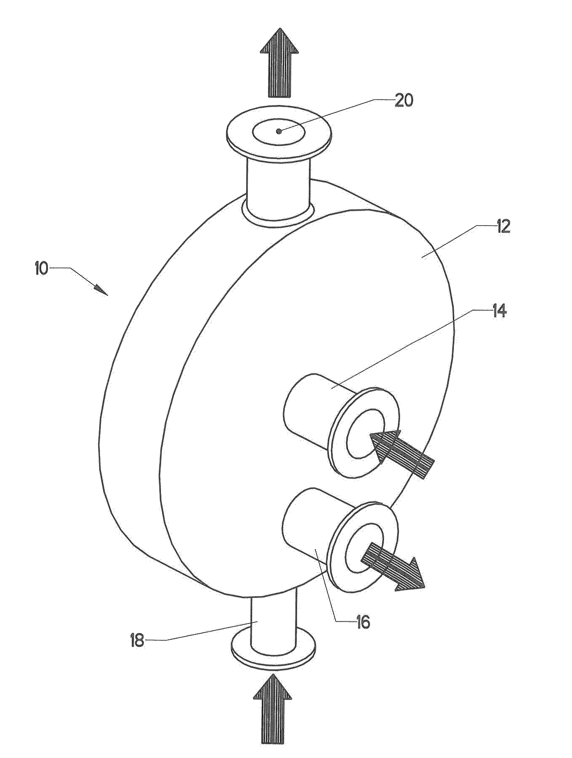
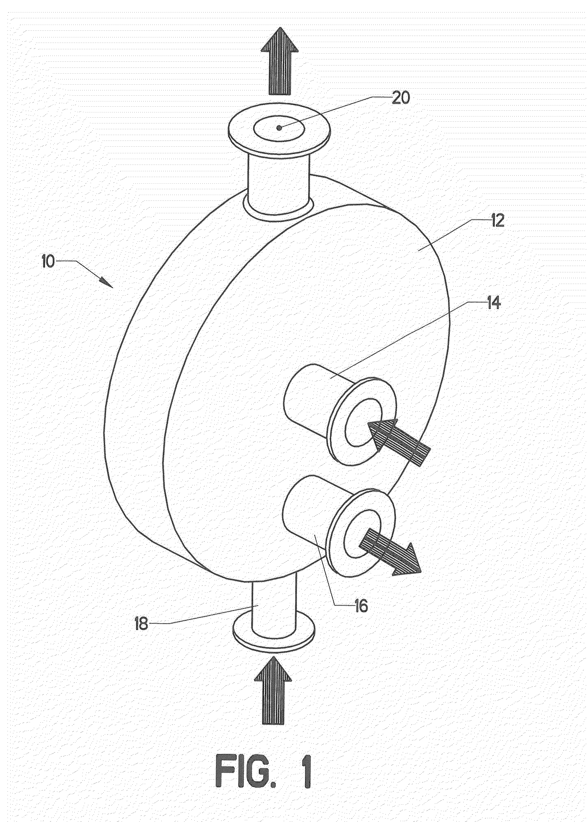
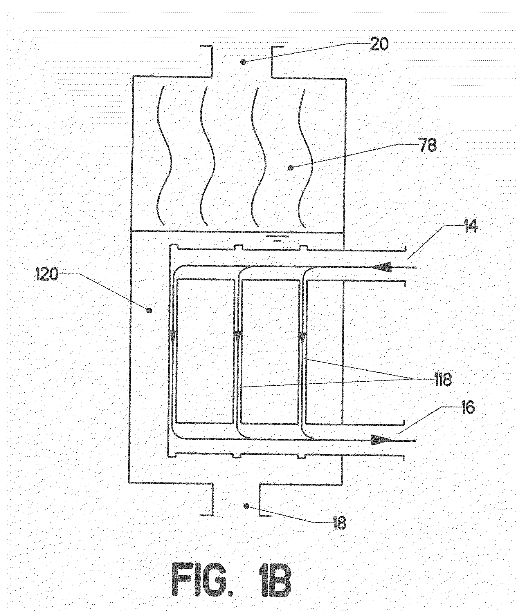
[0114]FIG. 1 shows a simplified version of a plate-type heat exchanger. Heat exchanger 10 includes many components enclosed within pressure vessel 12. The heat exchanger is configured to transfer heat between a primary fluid and a secondary fluid. The prim...


PUM


Abstract

A falling film plate type heat exchanger. The heat exchanger includes a pressure vessel surrounding an encapsulated stack of plates. Each plate has a primary fluid side and a secondary fluid side. The primary fluid will be a refrigerant—such as R-134a. The secondary fluid will typically be water. A film of refrigerant is applied to the primary fluid side of each plate, where it evaporates by absorbing heat from the secondary fluid on the other side of the plate. The invention uses embossed patterns on the plates to direct the flow of the primary and secondary fluids in a desired pattern. Further, the primary fluid side of each plate has a roughened surface treatment to increase the effective surface area and thereby increase the heat transfer rate.

Description

CROSS-REFERENCES TO RELATED APPLICATIONS[0001]This is a non-provisional application filed under 37 C.F.R. §1.53(c), which claims the benefit of an earlier-filed provisional application. The earlier provisional application was filed on Nov. 20, 2009 and was assigned application Ser. No. 61 / 281,691.STATEMENT REGARDING FEDERALLY SPONSORED RESEARCH OR DEVELOPMENT[0002]Not Applicable.MICROFICHE APPENDIX[0003]Not ApplicableBACKGROUND OF THE INVENTION[0004]1. Field of the Invention[0005]This invention relates to the field of heat exchangers. More specifically, the invention comprises a falling film liquid-to-liquid plate type heat exchanger featuring an enhanced surface on the primary fluid side.[0006]2. Description of the Related Art[0007]Heating, ventilation, and cooling (“HVAC”) systems employ at least two heat exchangers in a circulating loop of refrigerant. One heat exchanger is used to reject heat. This device is typically known as a condenser. A second heat exchanger is used to abso...

Claims


Application Information

Patent Timeline
IPC IPC(8): F28D15/00
CPCF28D3/00F28F25/06F28F3/042F28D2021/0071
Inventor RINGWALDT, SAMUEL ALEXANDER
Owner RINGWALDT SAMUEL ALEXANDER
Learn More