
Mass Spectrometer

a mass spectrometer and mass spectrometer technology, applied in mass spectrometers, stability-of-path spectrometers, separation processes, etc., can solve the problems of adverse dispersion of ions, ineffective use of direct-current electric fields, and inability to enhance ion transport efficiency, so as to enhance the ion transport efficiency of off-axis ion guides

Inactive Publication Date: 2011-05-26
SHIMADZU CORP
View PDF6 Cites 6 Cited by
  • Summary
  • Abstract
  • Description
  • Claims
  • Application Information

AI Technical Summary

Benefits of technology

[0016]The present invention has been developed in view of the aforementioned problems, and the objective thereof is to appropriately utilize a direct-current electric field in the ion optical axis direction to achieve a high ion transport efficiency and improve the analysis sensitivity in a mass spectrometer including a radio-frequency ion guide for transporting sequentially injected ions to the subsequent stage by using a radio-frequency electric field and the collisional cooling method.
[0017]To cool ions by using a collision with gas, it is necessary that the ions proceed at a certain degree of speed. To prevent ions from remaining inside the ion guide, it is necessary to give energy to them by an accelerating electric field. However, if ions which have been sufficiently cooled by collision and which are converged around the ion optical axis are forcedly given kinetic energy by the accelerating electric field, the ions collide with a cooling gas and have a velocity component in the direction orthogonal to the ion optical axis; therefore, the ions are adversely dispersed (or move away from the ion optical axis). Given this problem, the inventors of the present invention have conceived a new idea for setting a direct-current electric field in an ion guide. According to this idea, the ion transport region, through which ions pass, is not viewed as a single unit but is divided into plural regions along the ion optical axis direction, and an optimal direct-current electric field is created in each of these regions to improve the ion transport efficiency for each region.
[0022]When entering the ion guide, ions have a somewhat large amount of kinetic energy. Therefore, ions that collide with a cooling gas in the anterior portion of the ion guide may have a relatively large amount of kinetic energy in the direction orthogonal to the ion optical axis direction (or the radial direction) depending on the angle of collision. In order to efficiently transport such ions to the downstream area of the ion guide, ions headed in the radial direction need to be accelerated in the ion optical axis direction. To this end, in the anterior divided transport region of the ion guide in which a collisional cooling proceeds, it is necessary to form a relatively large direct-current electric field in the ion optical axis direction. Meanwhile, ions that have traveled to the posterior divided transport region of the ion guide have a small amount of kinetic energy both in the ion optical axis direction and in the radial direction due to the collisional cooling in the preceding phase. If these ions are accelerated by a large direct-current electric field from this state, a portion of the kinetic energy will be distributed from the ion optical axis direction to the radial direction by the collision of gases. This reduces the effect of converging the ion beam, resulting in a relative decrease in the ion transport efficiency. Given this factor, in order that sufficiently collisional-cooled ions are ejected from the ion guide while remaining converged around the ion optical axis direction as much as possible, the intensity of the direct-current electric field in the ion optical axis direction in the divided transport region near the exit plane of the ion guide is relatively decreased compared to that in the anterior divided transport region.
[0024]In the mass spectrometer according to the present invention, ions which have been sufficiently converged around the ion optical axis by a collisional cooling are not spatially dispersed and are ejected from the ion guide to be sent into the subsequent stage. Furthermore, the ions are prevented from remaining inside the ion guide due to an excessive reduction of the kinetic energy of the ions by a collisional cooling. Therefore, compared to conventional apparatuses, the ion transport efficiency is further increased, and a larger amount of ions can be transported into the acceptance area of a mass separator in the subsequent stage, such as a quadrupole mass spectrometer (or mass filter); consequently, the ion detection sensitivity can be enhanced.
[0028]Alternatively, in the case where the transport region is divided into three or more divided transport regions, the intensity of the direct-current electric field may be appropriately set for each of the divided transport regions. In this case, assuming that the transport region is divided into N divided transport regions, the electric field intensity is set for the N−1 divided transport regions from the side of the ion entrance plane in such a manner that the convergence of ions by a collisional cooling finishes around the boundary between the N−1st divided transport region and the Nth divided transport region. Further, the intensities of the electric field in the N−1 divided transport regions may be appropriately distributed so that the ion transport efficiency for the ions for which a collisional cooling is in progress is optimal. A typical example where N≧3 is appropriate is an off-axis ion guide in which the ion optical axes in the ion guide are out of alignment. In an off-axis ion guide, the optimal direct-current electric field in the ion optical axis direction is different between in the area where ions injected from the injection end substantially travel straight (excluding the oscillation by the radio-frequency electric field) and in the off-axis area having an optical axis oblique to the optical axis of the ions traveling straight. Given this factor, it is possible that the area where ions travel straight and the off-axis area are each regarded as an individual different divided transport region, and the intensities of their direct-current electric fields are independently set to enhance the ion transport efficiency of the off-axis ion guide.

Problems solved by technology

Hence, the direct-current electric field is not necessarily used effectively in terms of enhancing the ion transport efficiency.
However, if ions which have been sufficiently cooled by collision and which are converged around the ion optical axis are forcedly given kinetic energy by the accelerating electric field, the ions collide with a cooling gas and have a velocity component in the direction orthogonal to the ion optical axis; therefore, the ions are adversely dispersed (or move away from the ion optical axis).

Method used


Image

  • Mass Spectrometer
  • Mass Spectrometer
  • Mass Spectrometer

Examples


first embodiment

[0065]An embodiment (the first embodiment) of the mass spectrometer according to the present invention will be described with reference to the accompanying drawings.

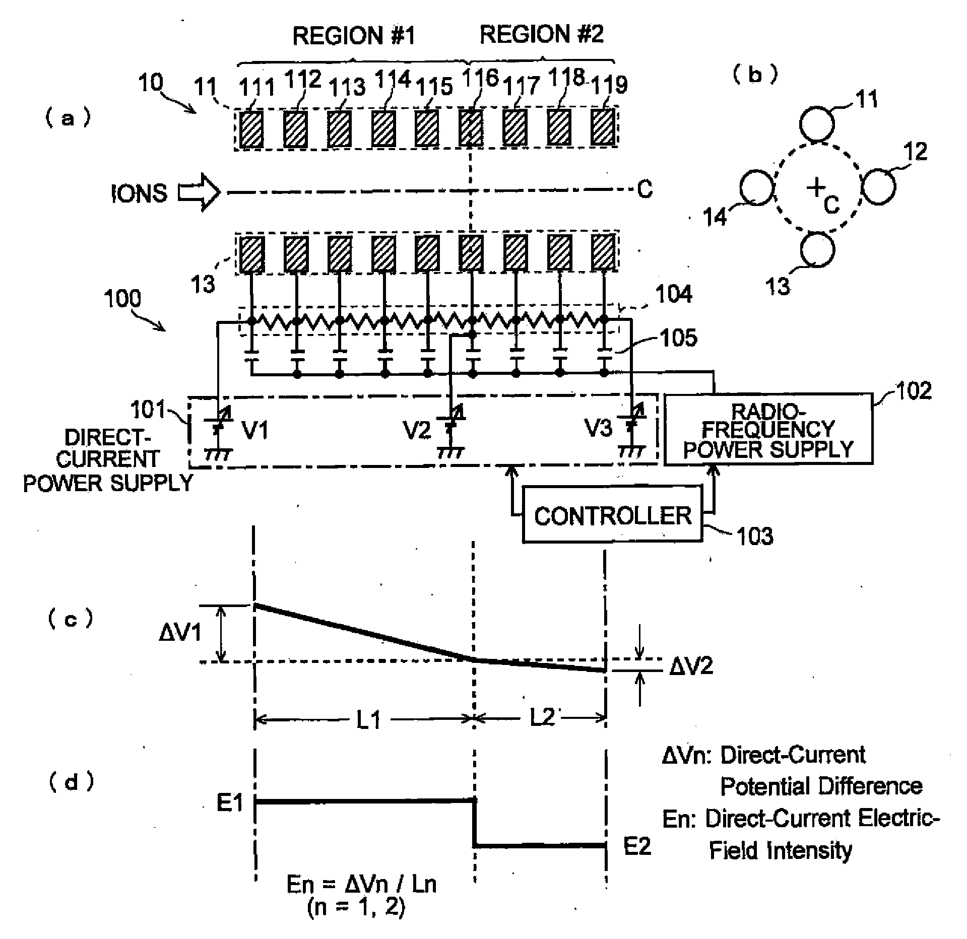
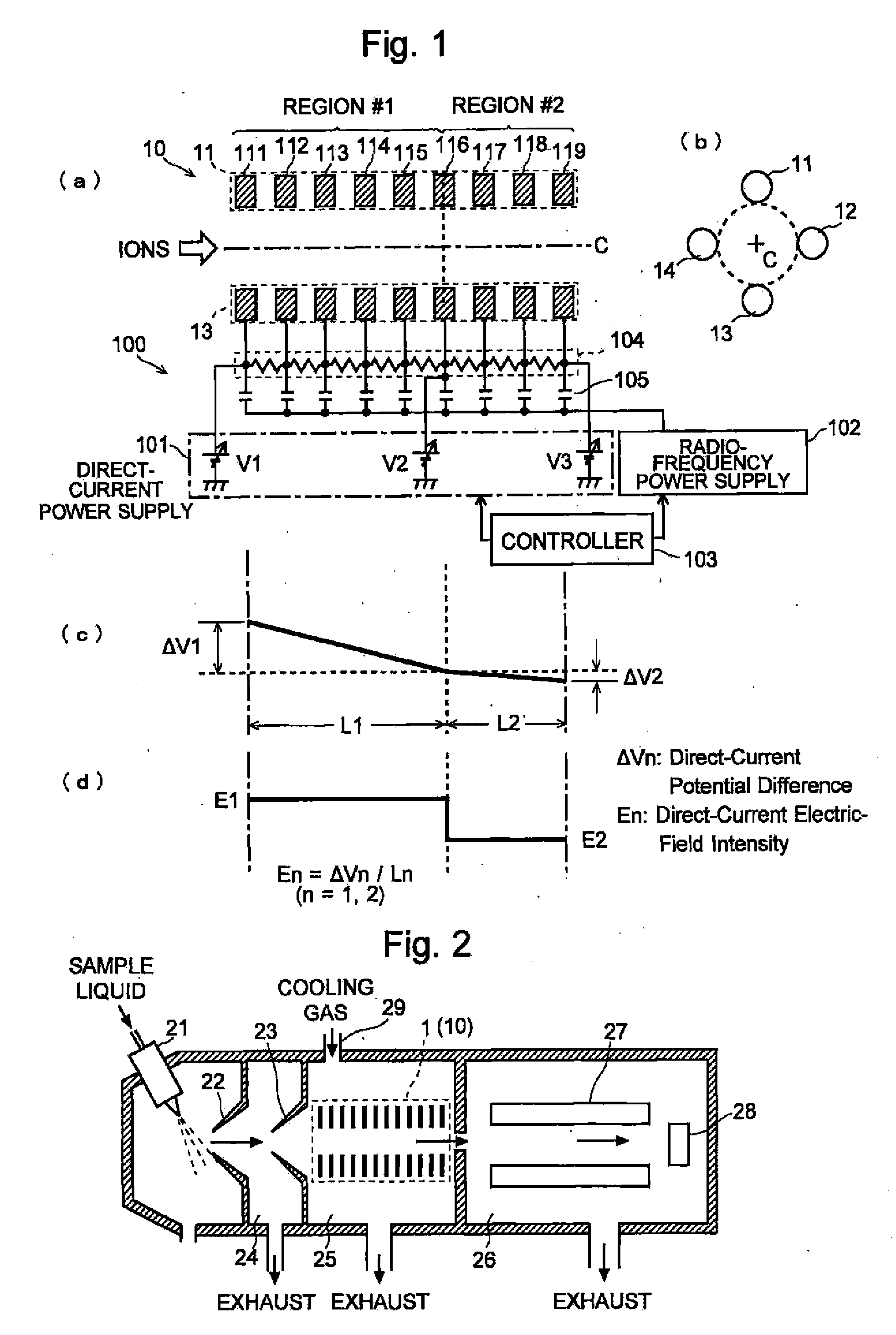
[0066]FIG. 2 is a schematic configuration diagram of the mass spectrometer according to the first embodiment, and FIG. 1 is a schematic configuration diagram of the ion guide in the mass spectrometer of the present embodiment and diagrams for explaining the operation thereof. In this mass spectrometer, an ESI ion source is used as an atmospheric pressure ion source.

[0067]As shown in FIG. 2, in this mass spectrometer, a sample liquid is injected to the ESI probe 21, and atomized into a space at substantially atmospheric pressure from the probe 21, so that the sample components are ionized. The generated ions are introduced into the first intermediate vacuum chamber 24 thorough the sampling cone (nozzle), and then introduced into the second intermediate vacuum chamber 25 through the skimmer 23. In the second intermediate v...

modification example

of the First Embodiment

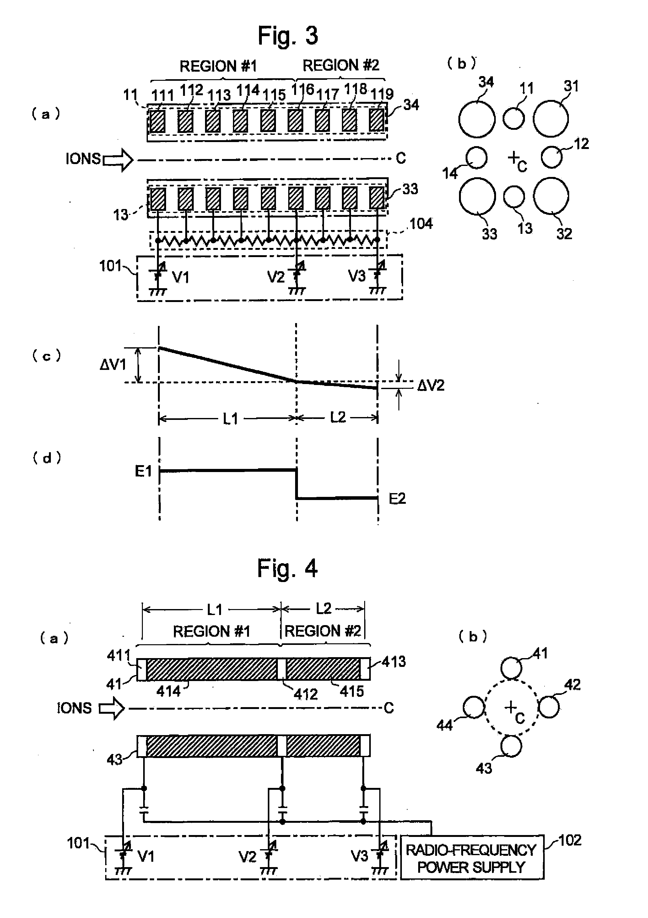
[0082]A modification example of the ion guide 1 which was described in the aforementioned first embodiment is shown in FIGS. 3 through 5.

[0083]In the first embodiment, a radio-frequency voltage which is superimposed on direct-current voltage is applied to virtual rod electrodes 11 through 14. Each voltage forms a radio-frequency electric field and a direct-current electric field in the space surrounded by the virtual rod electrode 11 through 14, respectively. Meanwhile, in the configuration shown in FIG. 3, auxiliary rod electrodes 11 through 14 for forming a direct-current electric field, which are composed of virtual rod electrodes similar to those in the first embodiment, are provided in addition to main rod electrodes 31 through 34 for forming a radio-frequency electric field. The main rod electrodes 31 through 34 are each made of a cylindrical (or column-shaped) conductor and have a typical quadrupole rod type configuration in which four electrodes are pr...

second embodiment

[0088]Next, an ICP-MS which is another embodiment (the second embodiment) of the mass spectrometer according to the present invention will be described. FIG. 6 is a schematic configuration diagram of this ICP-MS, and FIG. 7 is a schematic configuration diagram of the ion guide used in this ICP-MS and diagrams for explaining the operation thereof. The same or corresponding components as in the aforementioned first embodiment are indicated with the same numerals and the detailed explanations are omitted.

[0089]In this ICP mass spectrometer, a sample component is ionized in a plasma flame generated by the plasma torch of ICP ion source 50 under a substantially atmospheric pressure, and generated ions are injected to the ion guide placed in the second intermediate vacuum chamber 25 through the sampling cone 22 and the skimmer 23. In this configuration, an off-axis ion guide 6 is provided in order to prevent the light emitted from the plasma flame from entering the second intermediate vac...


PUM


Abstract

The present invention aims at enhancing the ion transport efficiency in an ion guide for transporting ions into the subsequent stage while converging the ions by using a collisional cooling method and a radio-frequency electric field. In the present invention, a transport region through which ions pass is divided into an anterior region #1 having a region length L1 and an posterior region #2 having a, region length L2, and the intensity of the direct-current electric field can be set for each of the regions. A direct-current electric field for appropriately accelerating ions is formed in the region #1 so that the collisional cooling of ions is sufficiently performed while the ions are traveling through the region #1 and the ions are sufficiently converged around the ion optical axis C near the end point of the region #1. Meanwhile, in the region #2, a direct-current electric field weaker than that of the region #1 is formed in order to make the converged ions move to the exit plane without allowing them to be dispersed. Consequently, the ions are transported in a sufficiently converged form without remaining in the ion guide, which can achieve a high transport efficiency.

Description

[0001]The present invention relates to a mass spectrometer. More precisely, it relates to an ion transport optical system for transporting an ion or ions in a mass spectrometer.BACKGROUND OF THE INVENTION[0002]In general, a mass spectrometer is composed of: an ion source for ionizing a sample molecule or a sample atom; a mass analyzer for separating ions in accordance with their mass-to-charge ratio and detecting the ions; and an ion transport optical system, which is placed between the ion source and the mass analyzer, for transporting the ions generated by the ion source. In a mass spectrometer which performs an MS / MS analysis or which uses a reaction process of a reaction gas, a collision chamber is provided between the ion source and the mass analyzer. Such a collision chamber can be considered to be included in an ion transport optical system in that the collision chamber transports ions to the mass analyzer.[0003]When ions are transported under an atmosphere where gas remains ...

Claims


Application Information

Patent Timeline
IPC IPC(8): H01J49/42
CPCH01J49/062H01J49/0481
Inventor YASUNO, MOTOHIDEOGAWA, KIYOSHINISHI, NOBUHIKO
Owner SHIMADZU CORP
Learn More