Tissue resurfacing

a tissue resurfacing and tissue technology, applied in the field of electronic keys, can solve the problems of scar tissue on the skin, increase in the temperature of the skin, and damage to the attractiveness of the skin, so as to minimize the possibility of variations in the energy being delivered, maximize the life of the instrument, and avoid the effect of degradation

Inactive Publication Date: 2011-05-26
KREOS CAPITAL III UK +1
View PDF53 Cites 54 Cited by
  • Summary
  • Abstract
  • Description
  • Claims
  • Application Information

AI Technical Summary

Benefits of technology

[0047]The present invention allows for the control of the energy delivered, whether in single or multiple sessions, such that the useful life of the instrument is maximized without risking the degradation of the instrument. Degradation of the instrument is to be avoided so as to minimize the possibility of variations in the energy being delivered to the skin being treated, and hence the effect the treatment may have on the tissue to be treated.

Problems solved by technology

Additionally skin frequently contains scar tissue, the appearance of which is considered by some people to be detrimental to their attractiveness.
This molecular dissociation kills the cells, and as a side effect also gives rise to an increase in temperature of the skin.

Method used


Image

  • Tissue resurfacing
  • Tissue resurfacing
  • Tissue resurfacing

Examples


Embodiment Construction

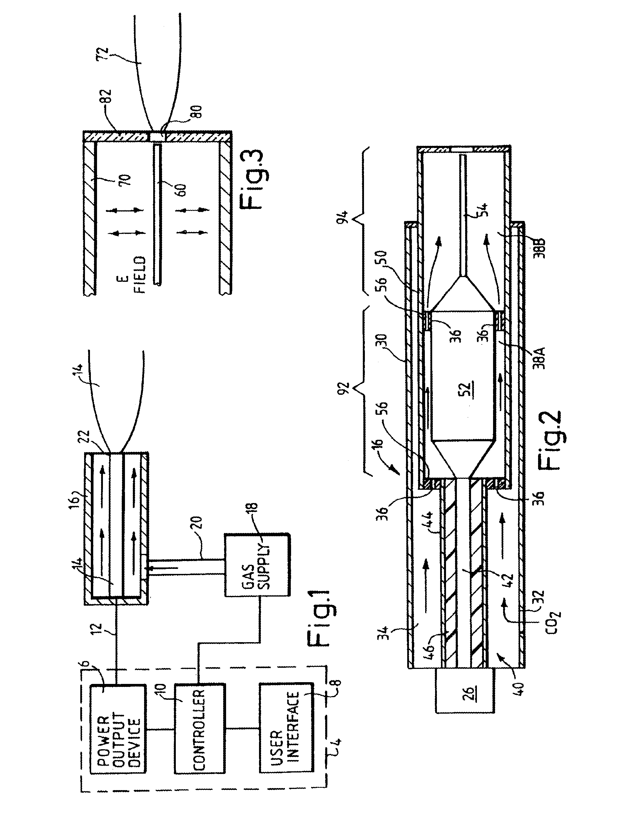
[0073]Referring to FIG. 1, the principle of operation of embodiments of the invention will now be described. A surgical system comprises a generator 4 which includes a power output 6, typically in the form of an oscillator and an amplifier, or a thermionic power device, and a user interface 8 and a controller 10. The generator produces an output which is coupled via a feed structure including a cable 12 to an electrode 14 of an instrument 16. The system further includes a supply 18 of gas, which is supplied to the instrument by means of a pipe 20. The gas is preferably a gas that enables relatively high energy to be delivered to the tissue per unit energy delivered into the gas at the instrument. Preferably the gas should include a diatomic gas (or gas having more than two atoms), for example, nitrogen, carbon dioxide or air. In use, the generator operates to establish an electric field in the region of the tip 22 of the electrode. Gas from the supply 18 is passed through the electr...


PUM


Abstract

In an electonic key associated with a device for skin treatment there is a housing and an integrated circuit, the integrated circuit is positioned within the housing, wherein the device for treating human tissue comprises a surgical instrument having a gas conduit terminating in a plasma exit nozzle, and an electrode associated with the conduit, and a radio frequency power generator coupled to the instrument electrode and arranged to deliver radio frequency power to the electrode in single or series of treatment pulses for creating a plasma from gas fed through the conduit, the pulses having durations in the range of from 2 ms to 100 ms.

Description

CROSS REFERENCE TO RELATED APPLICATIONS[0001]The present application is a Continuation in Part of U.S. application Ser. No. 11 / 354,880 filed Feb. 16, 2006 (now U.S. Pat. No. 7,785,322); which claims the benefit of U.S. Provisional Application Ser. No. 60 / 653,480 filed Feb. 17, 2005 and which is also a Continuation in Part of U.S. application Ser. No. 10 / 792,765 filed Mar. 5, 2004 (now U.S. Pat. No. 7,335,199); which is a Continuation in Part of U.S. application Ser. No. 09 / 789,550 filed Feb. 22, 2001 (now U.S. Pat. No. 6,723,091); which claims the benefit of U.S. Provisional Application Ser. No. 60 / 183,785 filed Feb. 22, 2000, which are each incorporated herein by reference in their entireties.BACKGROUND OF THE INVENTION[0002]This disclosure relates to an electronic key associated with a device for treating human tissue and a dielectric tube arranged for use with a gas plasma tissue resurfacing instrument.[0003]Human skin has two principal layers: the epidermis, which is the outer l...

Claims


Application Information

Patent Timeline
Patent Type & Authority Applications(United States)
IPC IPC(8): H01J7/24
CPCA61B18/042A61B2017/00725A61B2017/00199
Inventor PENNY, KEITH
Owner KREOS CAPITAL III UK
Why Eureka
Try Eureka