
Method and Apparatus for Pressure Control of Glass-Making Thickness-Control Zone

Inactive Publication Date: 2011-06-02
CORNING INC
View PDF11 Cites 34 Cited by
  • Summary
  • Abstract
  • Description
  • Claims
  • Application Information

AI Technical Summary

Benefits of technology

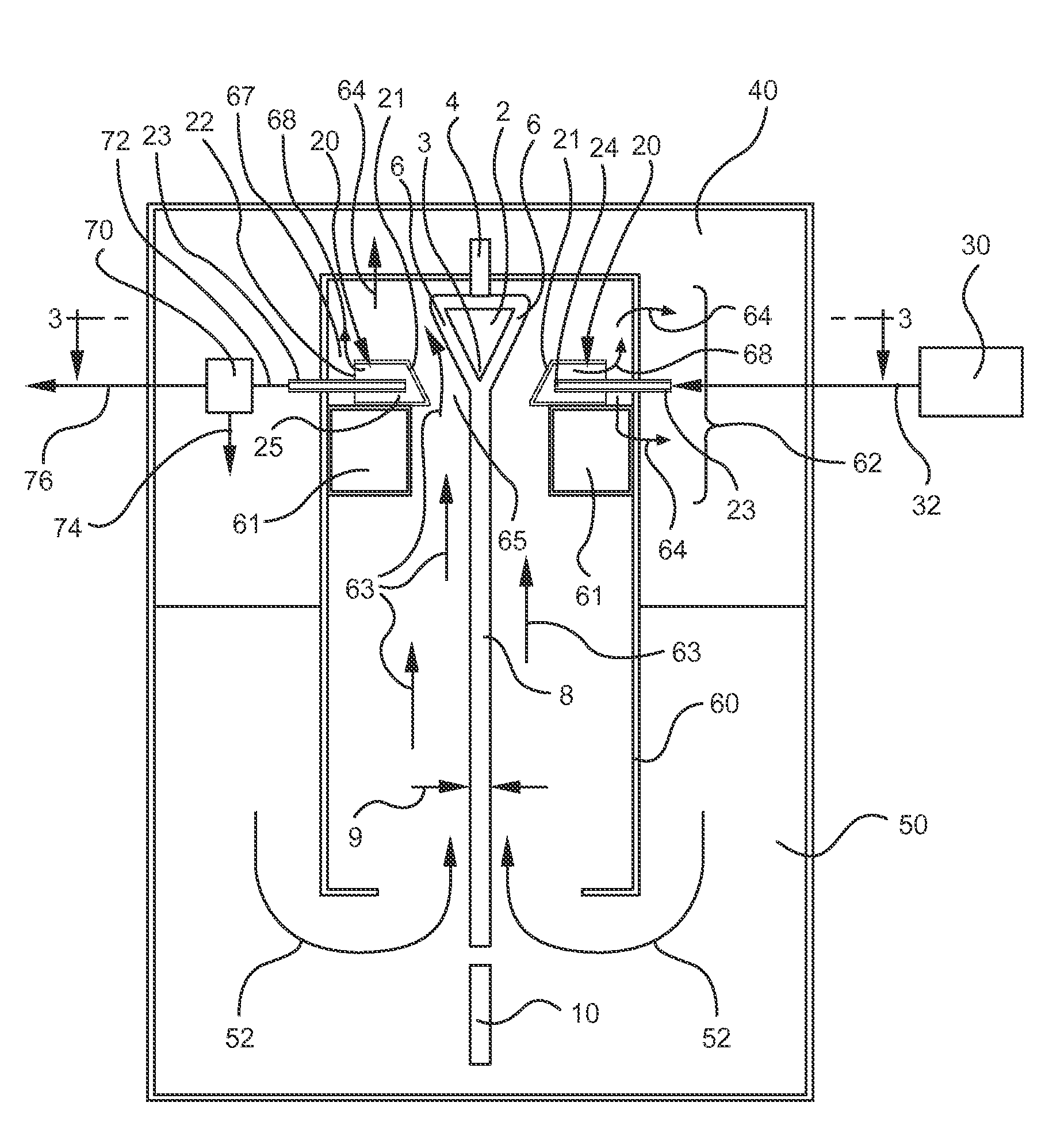
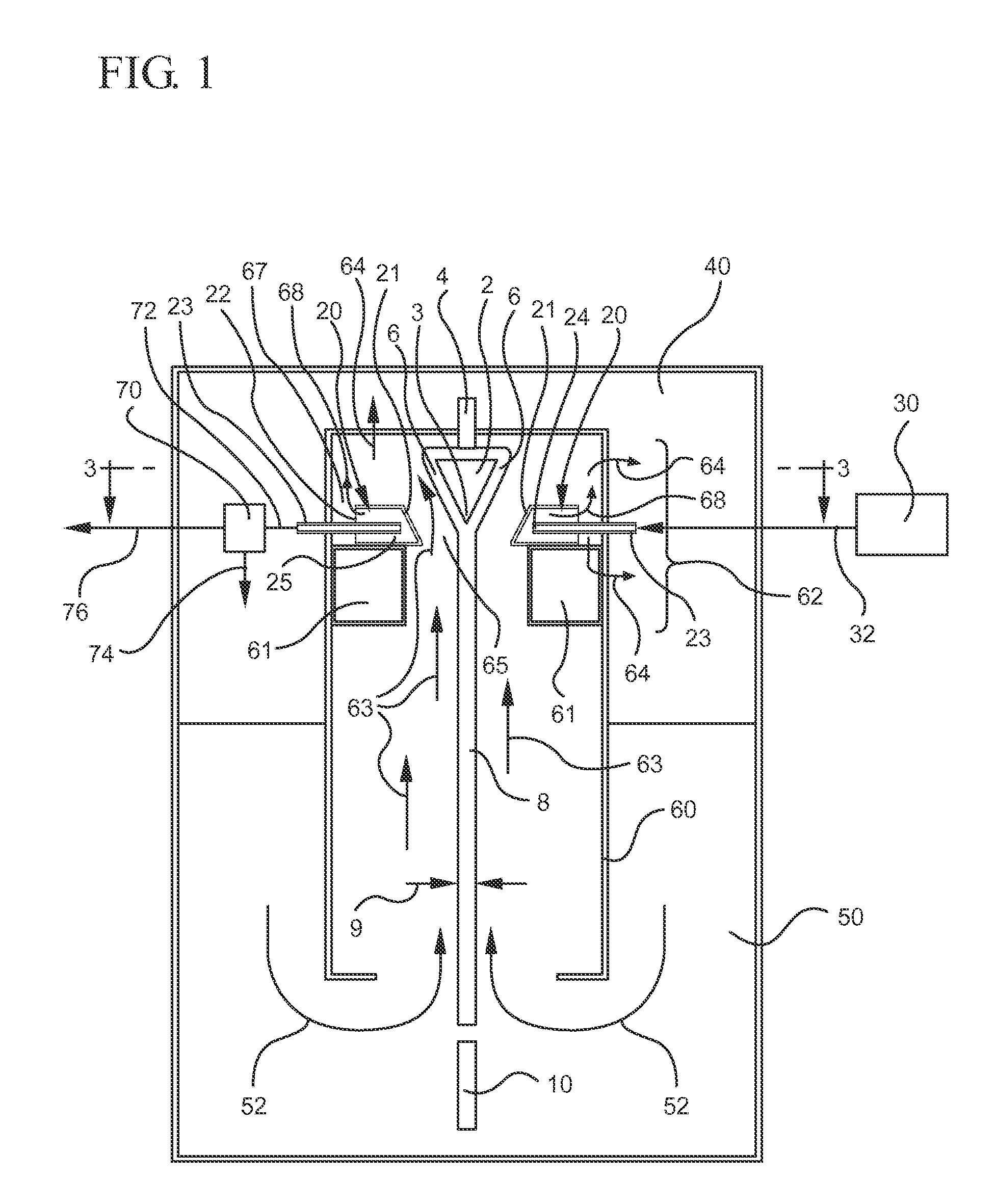
The present disclosure sets forth ways to manage pressure within the muffle door relative to pressures in the FDM enclosure, and in an upper chamber disposed outside the FDM enclosure, so as to minimize or control undesired gas flows that would adversely affect thickness control.
According to one pressure-management technique, the pressure in the muffle door is managed so as to be less than the pressure at a location that is within the FDM enclosure as well as both outside and adjacent to the muffle door. For example, the location may be between the muffle door housing and the glass or glass ribbon. In the event of a crack or unintended opening in the muffle door housing, for example, this pressure difference reduces or prevents gas flow toward the ribbon and, thereby, undesired thickness variation.
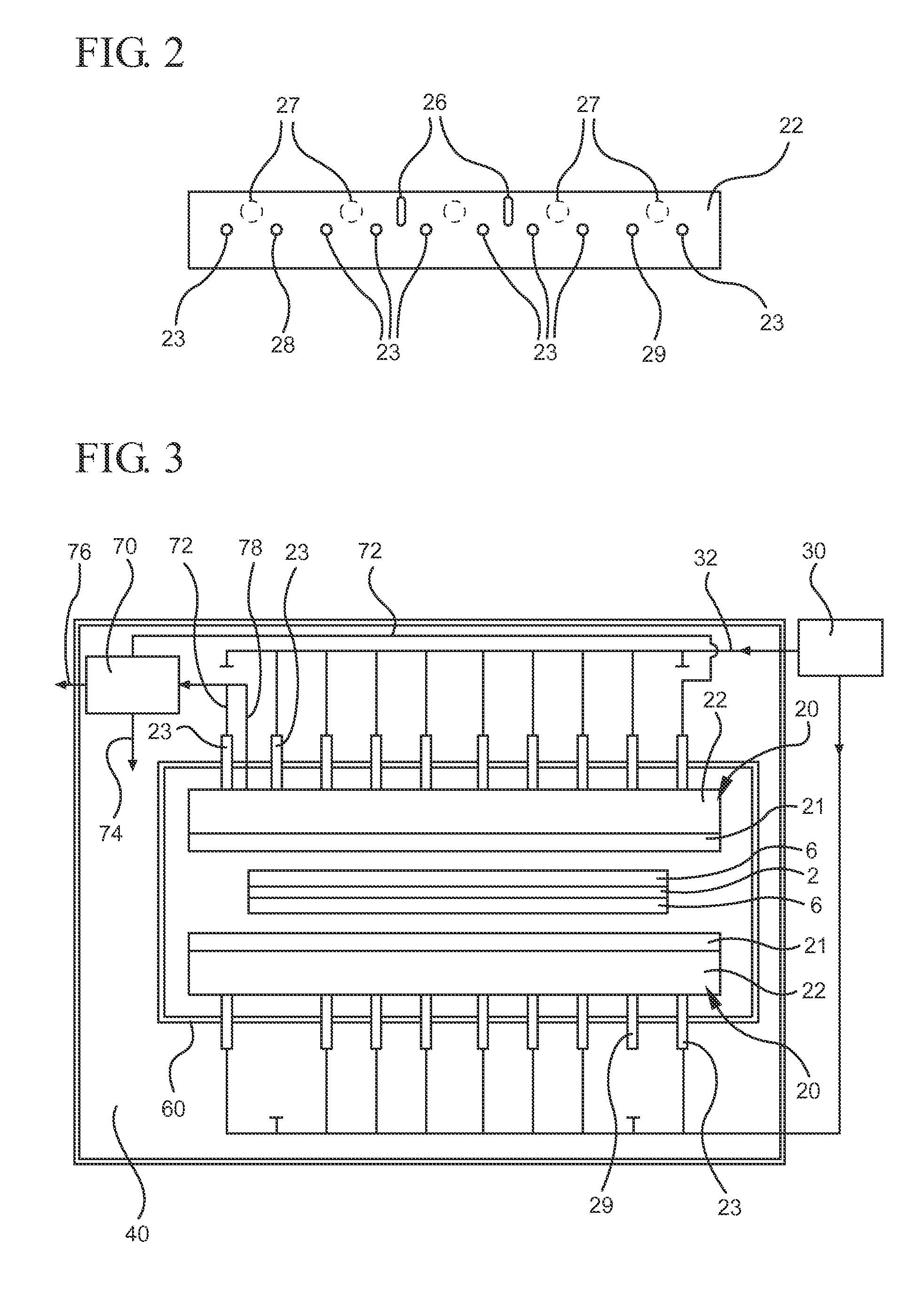
There are various ways to carry out the first pressure management technique. For example, gas flow out of the muffle door housing may be managed by: increasing the size of the existing venting holes in the muffle door housing; increasing the number of venting holes by making new holes in the muffle door housing; connecting the muffle door housing to an air handler to either passively or actively remove gas from the muffle door housing; disconnecting one or more of the existing fluid-inlet tubes from its fluid source; and / or removing one or more of the existing fluid-inlet tubes. Alternatively, or in addition, the pressure in the FDM enclosure may be increased. These ways may be used individually, or in combination with one another.
According to a second pressure-management technique, the pressure in the muffle door is managed so as to be greater than the pressure in a chamber that is disposed around the outside of at least the portion of the FDM enclosure in which the muffle door is disposed. Accordingly, there is minimized an adverse affect on thickness due to any changes in pressure in the chamber that result in reduced gas flow from the muffle door housing.
According to a first aspect there is provided a method of producing a glass sheet with reduced thickness variation, the method including: drawing a glass ribbon from a forming body that is disposed within an enclosure; delivering fluid to a housing, that is disposed within the enclosure and facing the forming body, so as to control local thickness of the ribbon, wherein delivering fluid to the housing comprises delivering fluid from a fluid source through a plurality of tubes having outlets within the housing; maintaining a first pressure at a location that is in the housing, and maintaining a second pressure at a second location that is in the enclosure as well as both outside and adjacent to the housing, so that the second pressure is greater than the first pressure; and separating a glass sheet from the ribbon.

Problems solved by technology

It has been discovered by the present inventors that certain events may cause the venting holes to not fully perform their intended function, which may cause a pressure build-up in the muffle door housing that results in undesired gas flows leaking out of the muffle door housing.
If undesired gas flows impinge upon the glass ribbon, they may adversely affect the thickness control by causing undesired thermal gradients in the glass.
When the uncontrolled and / or undesired gas-flows impinge on the glass ribbon, they cause undesired thickness variation in the ribbon.
In the event of a crack or unintended opening in the muffle door housing, for example, this pressure difference reduces or prevents gas flow toward the ribbon and, thereby, undesired thickness variation.

Method used


Image

  • Method and Apparatus for Pressure Control of Glass-Making Thickness-Control Zone
  • Method and Apparatus for Pressure Control of Glass-Making Thickness-Control Zone
  • Method and Apparatus for Pressure Control of Glass-Making Thickness-Control Zone

Examples


Embodiment Construction

In the following detailed description, for purposes of explanation and not limitation, example embodiments disclosing specific details are set forth to provide a thorough understanding of various principles of the present invention. However, it will be apparent to one having ordinary skill in the art, having had the benefit of the present disclosure, that the present invention may be practiced in other embodiments that depart from the specific details disclosed herein. Moreover, descriptions of well-known devices, methods and materials may be omitted so as not to obscure the description of various principles of the present invention. Finally, wherever applicable, like reference numerals refer to like elements.

As used herein, the singular forms “a,”“an” and “the” include plural referents unless the context clearly dictates otherwise. Thus, for example, reference to a “component” includes aspects having two or more such components, unless the context clearly indicates otherwise.

Direct...


PUM

PropertyMeasurementUnit
Pressureaaaaaaaaaa
Flow rateaaaaaaaaaa

Abstract

Managing pressure within a thickness-control-zone (muffle door) housing (20) relative to pressures in a glass-making machine enclosure (60) and an upper chamber (40)—that is disposed outside the enclosure—so as to minimize or control undesired airflows that would adversely affect thickness (9) of glass ribbon (8). According to one pressure-management technique, the pressure at a location (25) in the housing (20) is managed so as to be less than the pressure at a location (65) that is within the enclosure (60) as well as both outside and adjacent to the housing. In the event of a leak, as by a crack or unintended opening in the housing, for example, this pressure difference reduces or prevents airflow toward the ribbon and, thereby, undesired thickness variation in the ribbon. According to a second pressure-management technique, the pressure at location (25) is managed so as to be greater than the pressure in the upper chamber.

Description

BACKGROUND1. FieldThe present disclosure generally relates to controlling thickness, and more particularly thickness variation, in a glass ribbon as the ribbon is produced, wherein sheets are subsequently separated from the ribbon.2. Technical BackgroundA muffle door is used to control thickness gradients in a glass ribbon, from which there are separated glass sheets for making displays—for example, LCDs, plasma displays, OLEDs, and / or electroluminescent displays—and is generally described in U.S. Pat. No. 3,682,609. Air is blown through a bank of tubes of specific diameter a specific distance from a front plate designed of high thermal conductivity material that faces glass that is at a temperature above its softening point temperature. The objective is to generate thermal gradients across the ribbon, perpendicular to the direction of glass flow. These thermal gradients change the localized viscosity of the glass in one area relative to another, impacting the attenuation of the gla...

Claims


Application Information

Patent Timeline
IPC IPC(8): C03B15/02
CPCC03B17/067C03B17/064
Inventor CHALK, PAUL GREGORYKAHLOUT, AHDI ELMARKHAM, SHAWN RACHELLE
Owner CORNING INC
Learn More