
Band saw cutting apparatus and ingot cutting method

Active Publication Date: 2011-06-02
SHIN-ETSU HANDOTAI CO LTD
View PDF11 Cites 5 Cited by
  • Summary
  • Abstract
  • Description
  • Claims
  • Application Information

AI Technical Summary

Benefits of technology

[0016]The present invention was accomplished in view of the above-explained problems, and its object is to provide a band saw cutting apparatus and an ingot cutting method that can stably secure the quality of the ingot to be cut, increase the lifetime of the blade, and improve the productivity.
[0029]In the band saw cutting apparatus according to the present invention, the pulleys between which the blade is provided in a tensioned state is configured to be rotatable about an axis thereof in both directions, the ingot is cut with the blade driven to rotate in one direction, and after the cutting and before next cutting, the direction of driving to rotate the blade is changed into a direction opposite to the one direction to cut the ingot. The displacement amount of the edge deflection of the blade can be therefore suppressed to a low level by changing the direction of the edge deflection of the blade between before and after the change of the direction of driving to rotate the blade. The cutting precision of the ingot can be thereby stably secured, and the lifetime of the blade can be improved. In addition to these, the frequency of the dressing can be reduced, and the productivity can be improved.

Problems solved by technology

However, the operation greatly depends on an individual skill of the operator, and particularly with regard to the blade that is made thinner, it is thereby difficult to repair the edge deflection of the blade.
Therefore, there arises a problem that the ingot cannot be cut with stable quality and that the lifetime of the blade decreases.
Moreover, there is also a problem that process time increases by performing the dressing or tooling by the operator as described above so that productivity decreases.

Method used


Image

  • Band saw cutting apparatus and ingot cutting method
  • Band saw cutting apparatus and ingot cutting method
  • Band saw cutting apparatus and ingot cutting method

Examples


example

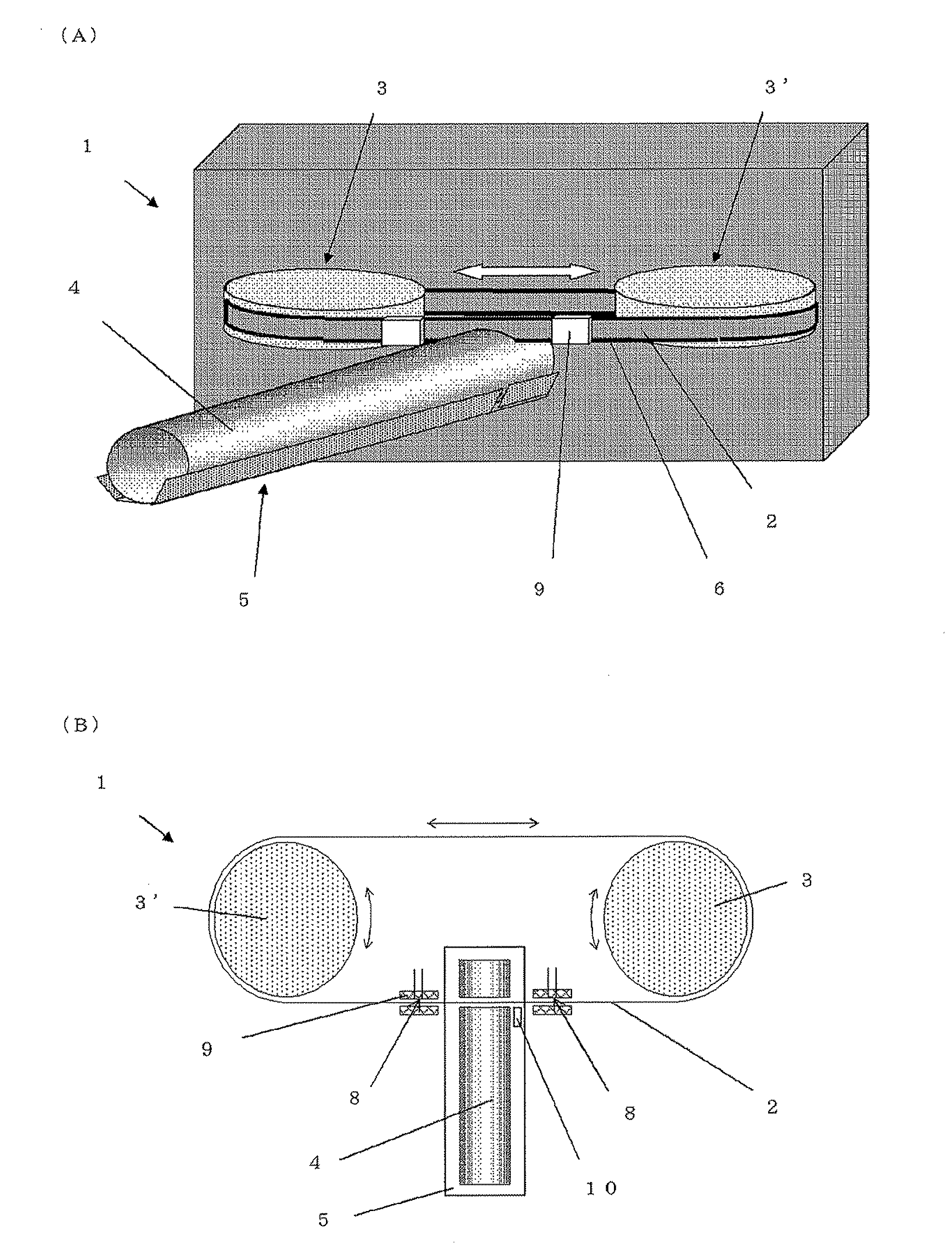
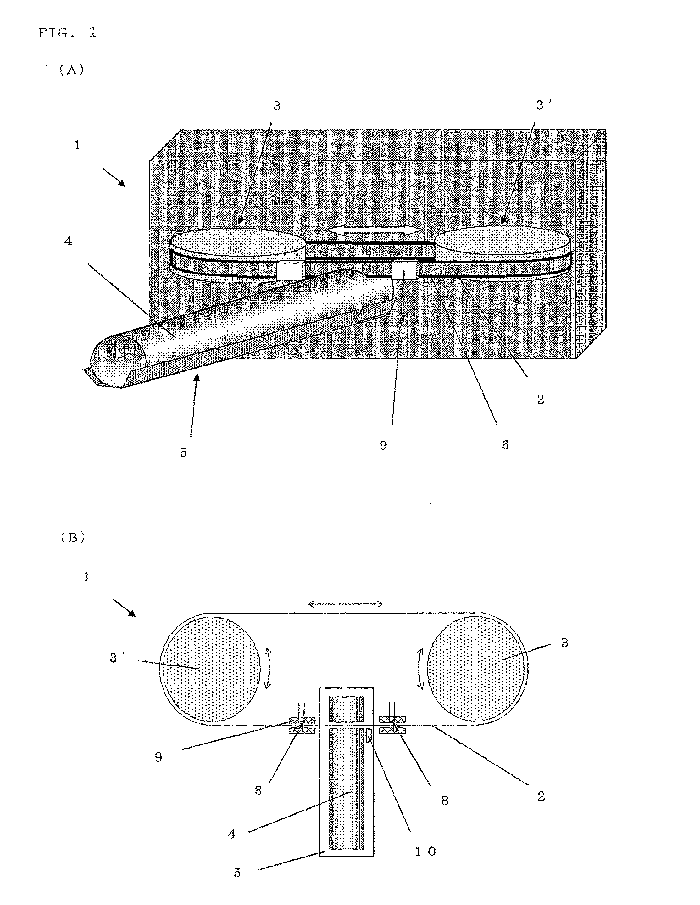
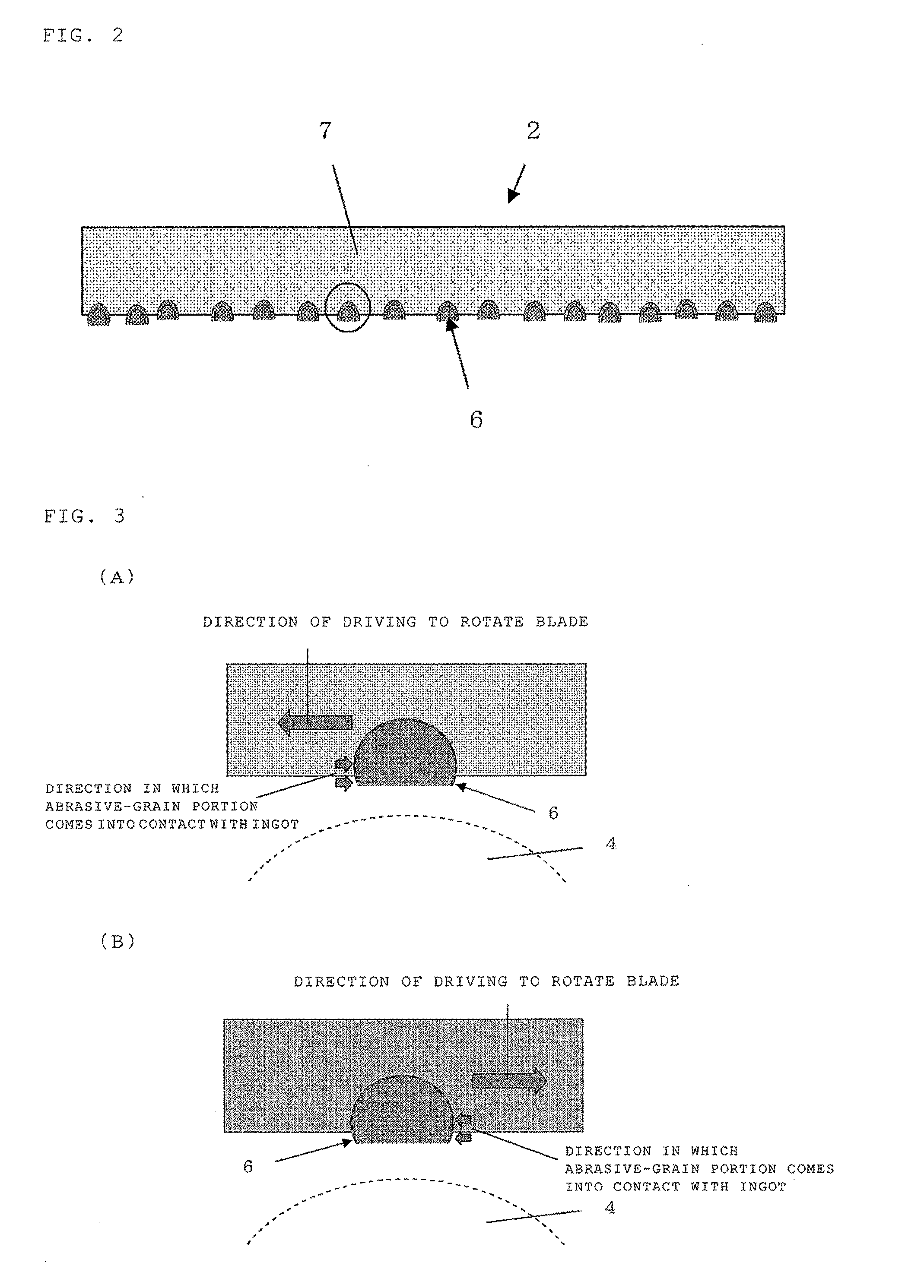
[0078]With the band saw cutting apparatus according to the present invention as shown in FIG. 1, the ingot was repeatedly cut into a block by the ingot cutting method according to the present invention. The displacement amount of the blade was measured with an eddy current sensor. After the cutting in which the measured displacement amount became 100 μm or more and before next cutting, the direction of driving to rotate the blade was changed to repeatedly cut. The number of cutting when the displacement amount of the blade became 100 μm or more next was evaluated. These were repeatedly carried out to evaluate the number of cutting when the displacement amount of the blade became 200 μm as the lifetime of the blade.

[0079]Here, the thickness of the base of the used blade was 0.3 mm, and the one shaft drive in which one pulley is driven to rotate by itself was configured. The tension for stretching the blade between the pulleys was 1.4 ton.

[0080]As a result, it was revealed that an ave...


PUM

PropertyMeasurementUnit
Thicknessaaaaaaaaaa

Abstract

The present invention is a band saw cutting apparatus including: a cutting table on which an ingot is horizontally placed; an endless-belt blade provided in a tensioned state between pulleys, the blade having a blade-abrasive-grain portion and a blade base; and a coolant spraying opening for spraying a coolant on the blade, the band saw cutting apparatus cutting the ingot by relatively feeding the blade from above to below, the blade being driven to rotate by rotating the pulleys, wherein the pulleys is configured to be rotatable about an axis thereof in both directions, and a direction of driving to rotate the blade can be changed to cut the ingot. As a result, there is provided a band saw cutting apparatus and an ingot cutting method that can stably secure the quality of the ingot to be cut, increase the lifetime of the blade, and improve the productivity.

Description

TECHNICAL FIELD[0001]The present invention relates to an ingot cutting apparatus for cutting an ingot, particularly a silicon ingot, pulled by the Czochralski method (the CZ method) and the like and a cutting method by using the same.BACKGROUND ART[0002]A silicon ingot produced by the CZ method and the like has a cylindrical body portion and cone-shaped end portions (a top portion and a tail portion). In processing of the silicon ingot, these cone-shaped end portions are cut away to separate the cylindrical body portion, and the body portion is cut into a plurality of blocks as needed. The blocks are thereafter subjected to processing for obtaining a wafer.[0003]An inner diameter slicer and an outer diameter slicer or the like have been frequently used for the case of the cutting processing of the cone-shaped end portions and the cutting processing of the body portion into a plurality of blocks. As the diameter of the wafer becomes larger in recent years, a band saw also has become ...

Claims


Application Information

Patent Timeline
IPC IPC(8): B28D5/04
CPCB23D55/06B28D5/045B28D1/127B24B27/06H01L21/304H01L21/30625H01L21/78
Inventor NISHINO, HIDEHIKOHIRANO, YOSHIHIROUCHIDA, JUNICHI
Owner SHIN-ETSU HANDOTAI CO LTD
Features
  • Generate Ideas
  • Intellectual Property
  • Life Sciences
  • Materials
  • Tech Scout
  • Unparalleled Data Quality
  • Higher Quality Content
  • 60% Fewer Hallucinations
Learn More