System for generation of power using solar energy

a solar energy and power generation technology, applied in the direction of steam generation using solar heat, electric generator control, machines/engines, etc., can solve the problems of high electricity cost, high cost of building a plant, and the use of solar energy for electricity generation uses a renewable energy sour

Inactive Publication Date: 2011-06-02
GENERAL ELECTRIC CO
View PDF15 Cites 106 Cited by
  • Summary
  • Abstract
  • Description
  • Claims
  • Application Information

AI Technical Summary

Benefits of technology

[0006]In accordance with another aspect of the present technique, an electricity generation system is presented. The electricity generation system includes a solar preheater for preheating compressed discharge air using a first portion of a heated solar fluid to generate heated compressed air, a combustor operatively coupled to the solar preheater to receive the heated compressed air from the solar preheater, burn a fuel using the heated compressed air to generate hot burned gas, a high pressure turbine operatively coupled to the combustor to receive the hot burned gas from the combustor, expand the hot burned gas to generate a first expanded gas, a reheater operatively coupled to the high pressure turbine to receive the first expanded gas from the high pressure turbine, combust a fuel using the first expanded gas to generate a first heated expanded gas, a low pressure turbine operatively coupled to the high pressure turbine and the reheater to expand the first heated expanded gas received from the reheater to generate the exhaust gas, a heat recovery steam generator connected to the low pressure turbine to generate vapor by heating a condensed fluid with the exhaust gas received from the low pressure turbine, and a solar evaporator / superheater operationally coupled to the heat recovery steam generator to receive a heated working fluid from the heat recovery steam generator, generate solar vapor by heating the heated working fluid using a second portion of the heated solar fluid, and a second turbine to drive a second generator using the vapor received from the heat recovery steam generator and the solar vapor received from the solar evaporator / superheater.

Problems solved by technology

However, usage of fossil fuel for the generation of electricity is dominated by the high cost of the fossil fuel and the depletion of natural resources, which in turn results in a high cost of electricity.
In contrast, usage of solar energy for the generation of electricity uses a renewable energy source but is dominated by high costs associated with building a plant.

Method used


Image

  • System for generation of power using solar energy
  • System for generation of power using solar energy
  • System for generation of power using solar energy

Examples


Embodiment Construction

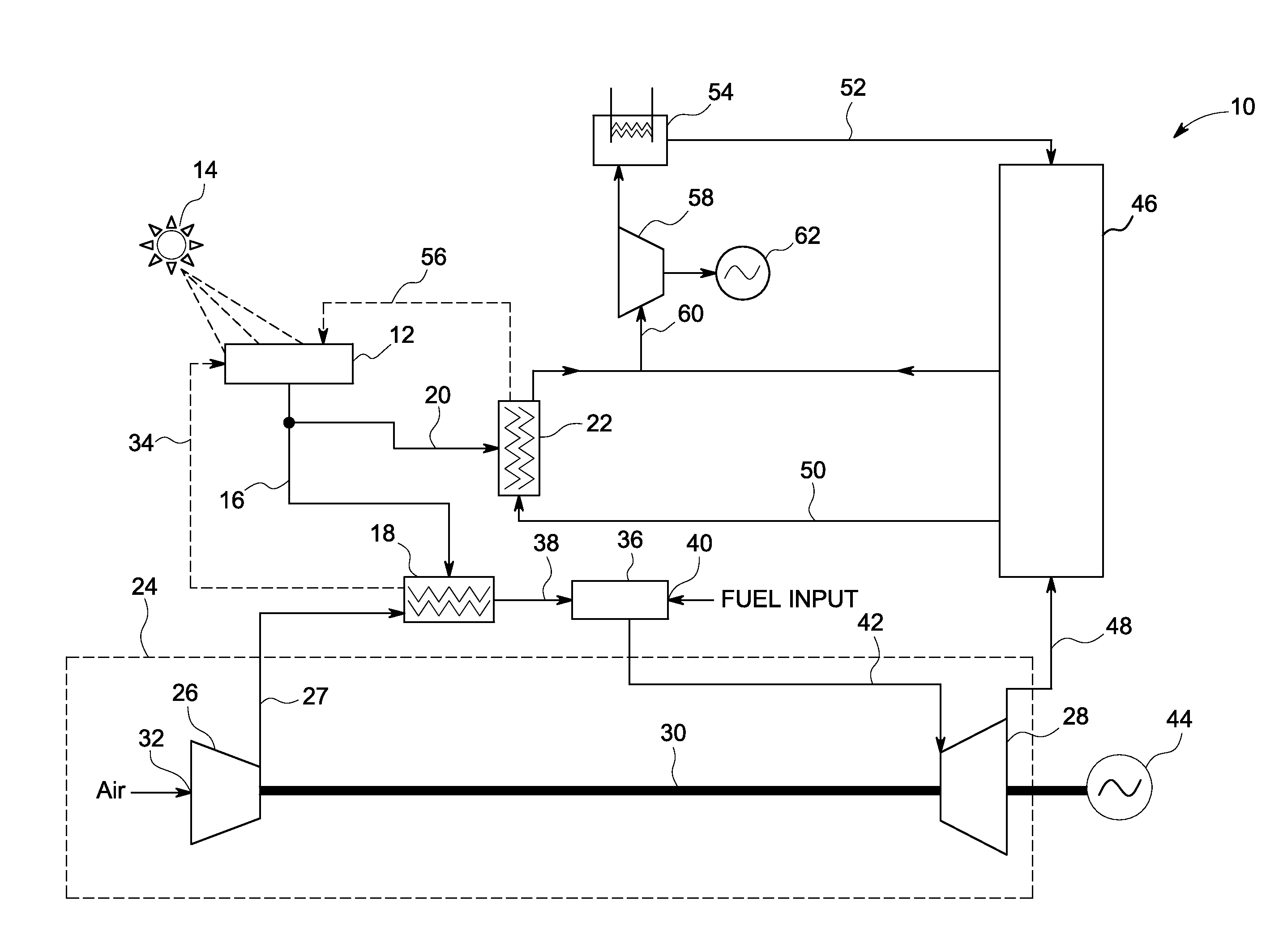
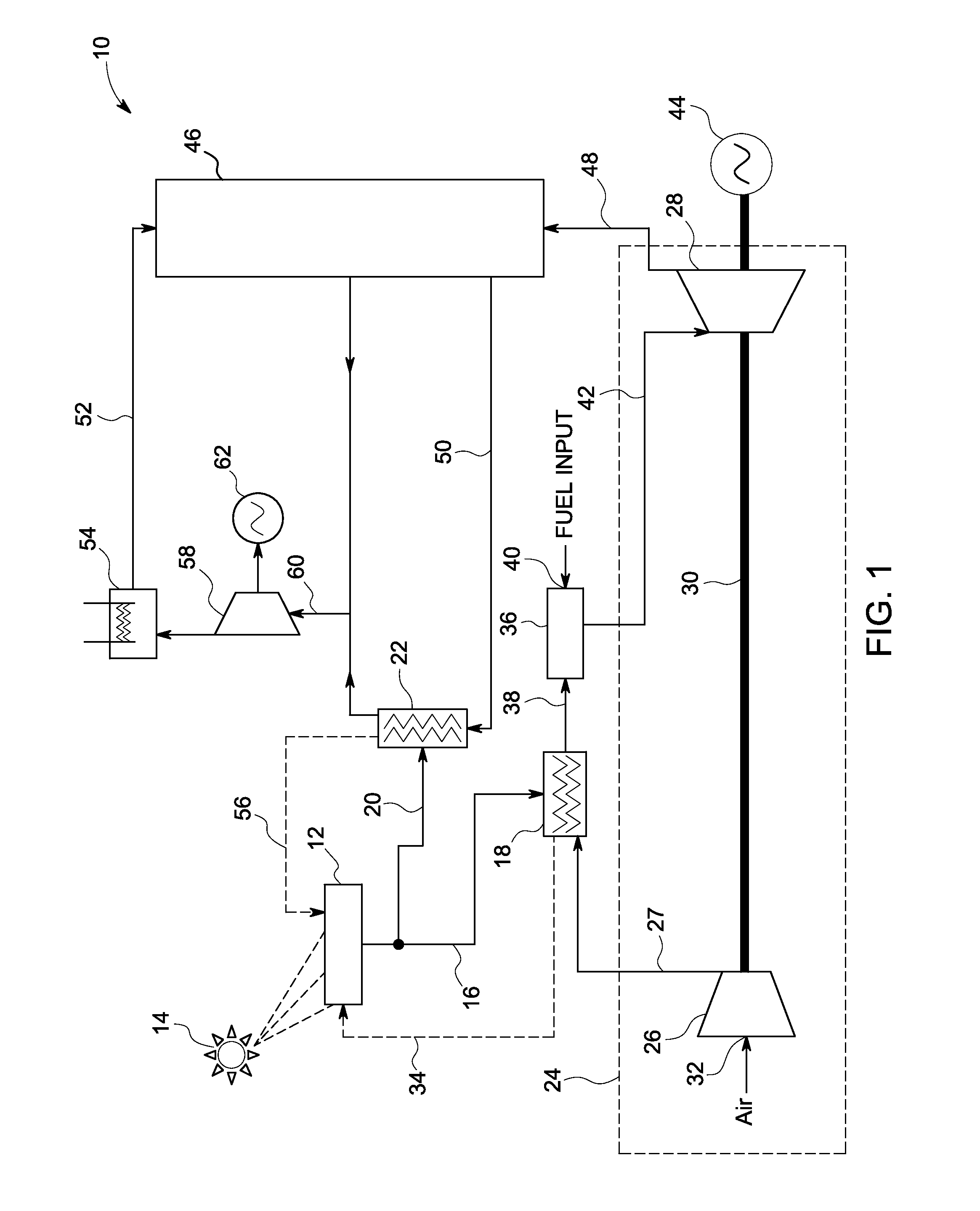
[0012]FIG. 1 is a diagrammatical view of one embodiment of an electricity generation system 10, in accordance with aspects of the present technique. More particularly, FIG. 1 illustrates the electricity generation system 10 for generation of electricity that uses a hybrid-combined cycle with solar preheating. As illustrated in FIG. 1, the electricity generation system 10 may include solar field and receivers 12 for concentrating sunrays from the sun 14 and absorbing heat of the sunrays. An exemplary solar field and receivers for concentrating sunrays will be described in greater detail with reference to FIG. 2. The solar field and receivers 12, for example, may include a reflecting parabolic dish with an absorbing receiver in the focal point, a parabolic trough with an absorber tube in the focal line, an array of mirrors known as heliostats that reflect sunrays onto a central receiver, linear Fresnel lenses or mirrors to focus the sunrays.

[0013]Furthermore, in one embodiment, the so...


PUM


Abstract

An electricity generation system is presented. The electricity generation system includes a solar preheater for preheating compressed discharge air, a combustor to receive the heated compressed air from the solar preheater, burn a fuel using the heated compressed air to generate hot burned gas, a first turbine to receive the hot burned gas from the combustor, expand the hot burned gas to generate exhaust gas, a heat recovery steam generator to receive the exhaust gas from the first turbine, generate vapor by heating a condensed fluid using the exhaust gas, a solar evaporator/superheater to receive a heated working fluid from the heat recovery steam generator, generate solar vapor by heating the heated working fluid, and a second turbine to drive a second generator using vapor and the solar vapor.

Description

BACKGROUND[0001]Generation of electricity is typically a process using other forms of energy and is often generated at a power station by electromechanical generators that are usually driven by heat engines. The heat engines may be fueled by chemical combustion, nuclear fission, or by other means, such as, kinetic energy of flowing water, wind, and the like. Further, solar power may also be used to drive a heat engine for generation of electricity.[0002]Electricity generation techniques using heat engines generally combust fossil fuel to generate electricity. However, usage of fossil fuel for the generation of electricity is dominated by the high cost of the fossil fuel and the depletion of natural resources, which in turn results in a high cost of electricity. In contrast, usage of solar energy for the generation of electricity uses a renewable energy source but is dominated by high costs associated with building a plant.[0003]It is therefore desirable to develop a design of a powe...

Claims


Application Information

Patent Timeline
Patent Type & Authority Applications(United States)
IPC IPC(8): F02C6/00F01K23/10F03G6/00
CPCF01K23/10F02C1/05F03G6/064Y02E20/16F22B1/006Y02E10/46F03G6/065
Inventor FREUND, SEBASTIAN WALTERLANG, KEVIN RICHARDPALAFOX, PEPE
Owner GENERAL ELECTRIC CO
Why Eureka
Try Eureka