Optical-type position detecting device, hand apparatus, and touch panel

a technology imaging device, which is applied in the direction of instruments, manufacturing tools, transportation and packaging, etc., can solve the problems of inability to detect the gripping force, long processing time of the imaging operation result, and high cost of optical-type position detecting device using imaging device, etc., to achieve accurate detection of contact, low cost, and superior responsiveness

Inactive Publication Date: 2011-06-02
COLUMBIA PEAK VENTURES LLC
View PDF21 Cites 27 Cited by
  • Summary
  • Abstract
  • Description
  • Claims
  • Application Information

AI Technical Summary

Benefits of technology

[0085]As described above, according to the optical-type position detecting device 10 of this embodiment, the light source device 11 forms the light intensity distribution L2Zab for separation distance detection in which the intensity changes in the direction of the normal line of the first face 41 on the first face 41 side (the detection region 10R) by emitting the detection light L2 from the second face 42 side of the translucent member 40 that is a side opposite to the first face 41 side of the translucent member 40 on which the target object Ob is located. In addition, the reflected light L3 that is reflected by the target object Ob and is transmitted to the second face 42 side of the translucent member 40 is detected by using the light detector 30. Here, in the light intensity distribution L2Zab for separation distance detection, there is a predetermined relationship between the separation distance LZ1 from the translucent member 40 and the intensity. Thus, when the relationship between the separation distance from the translucent member 40 and the intensity of the detection light is acquired in advance, the separation distance detecting section 53 of the position detecting unit 50 can detect a separation distance between the target object Ob and the translucent member 40 based on the result of light reception in the light detector 30. Therefore, according to this embodiment, an expensive imaging device or complex image processing requiring a processing time is not required. Accordingly, an optical-type position detecting device 10 that has superior responsiveness can be configured at low cost.
[0086]In addition, when the target object Ob is brought into contact with the translucent member 40, boundary reflection of the detection light L2 does not occur. Accordingly, the intensity of light received by the light detector 30 has a value that deviates from the light intensity distribution L2Zab for separation distance detection. Therefore, the separation distance detecting section 53 of the position detecting unit 50 can determine a position at the time when the intensity detected by the common light detector 30 becomes a value deviated from the light intensity distribution L2Zab for separation distance detection to be a position at which the target object Ob is brought into contact with the translucent member 40.
[0087]In addition, the first face 41 of the translucent member 40 has elasticity and an embedding property in regard to the target object Ob. Thus, when the target object Ob is brought into contact with the first face 41 of the translucent member 40, the first face 41 of the translucent member 40 is deformed so as to be embedded with the target object Ob. Accordingly, the state in which the target object Ob and the translucent member 40 are in proximity to each other is clearly switched completely to the state in which the target object Ob and the translucent member 40 are brought into contact with each other. Thus, when the target object Ob arrives at a position extremely close to being brought into contact with the translucent member 40, the intensity of detection light that is detected by the light detector 30 changes in a rapid manner. Accordingly, the separation distance detecting section 53 of the position detecting unit 50 can accurately detect the contact of the target object Ob with the translucent member 40.
[0088]In addition, according to this embodiment, when the target object Ob presses the first face 41 of the translucent member 40, the translucent member 41 is compressed so as to have a decreased thickness. In addition, the propagation characteristics may change depending on the material of the translucent member 40. Accordingly, the burial depth detecting section 56 of the position detecting unit 50 can detect the burial depth LZ2 (the amount of burial) of the target object Ob based on the result of light reception in the common light detector 30 at a time when the target object Ob presses the first face 41 of the translucent member 40. In addition, the first face 41 of the translucent member 40 has an embedding property in regard to the target object Ob. Thus, when the target object Ob presses the first face 41 of the translucent member 40, the first face 41 of the translucent member 40 is embedded with the target object Ob, and the boundary surface between the target object Ob and the first face 41 is in a stable state. Accordingly, since the reflection of detection light on the boundary surface between the target object Ob and the first face 41 is stable, the burial depth LZ2 (the relative position) of the target object Ob with respect to the translucent member 40 can be accurately detected in an optical manner.
[0089]In addition, according to this embodiment, since the contact of the target object Ob with the translucent member 40 can be accurately determined, the burial depth LZ2 of the target object Ob based on the contact position of the target object Ob with the translucent member 40 or the separation distance LZ1 of the target object Ob can be accurately detected.
[0090]Here, since the first face 41 of the translucent member 40 is formed from a silicone resin or silicone rubber, a configuration in which the first face 41 of the translucent member 40 has elasticity and an embedding property in regard to the target object Ob can be easily realized.

Problems solved by technology

However, there are problems in that an optical-type position detecting device using an imaging device is expensive and takes a long time to process the result of the imaging operation.
In addition, it is impossible to detect the gripping force at a time when the hand grips a target object from the imaged result acquired by the imaging device.
However, according to the technology disclosed in JP-A-2007-71564, although light reflected from a target object at a time when the target object presses the optical propagation medium is detected, the boundary state between the target object and the optical propagation medium is not stable.
Thus, according to the technology disclosed in JP-A-2007-71564, there is a problem in that the burial depth (the relative position of the target object with respect to the translucent member) of the target object at a time when the target object presses the optical propagation medium (translucent member) cannot be accurately detected.

Method used


Image

  • Optical-type position detecting device, hand apparatus, and touch panel
  • Optical-type position detecting device, hand apparatus, and touch panel
  • Optical-type position detecting device, hand apparatus, and touch panel

Examples


embodiment 1

Entire Configuration

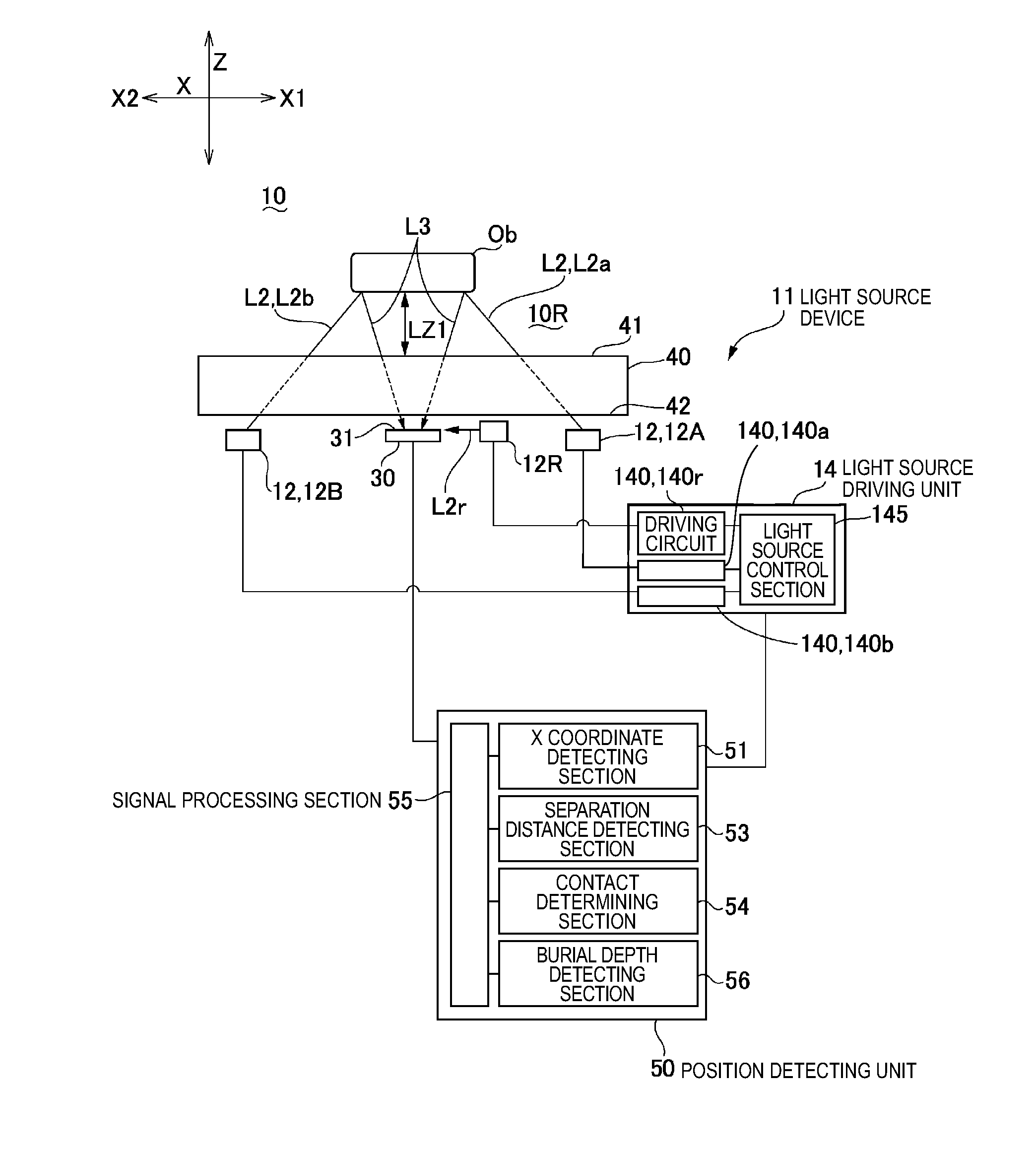
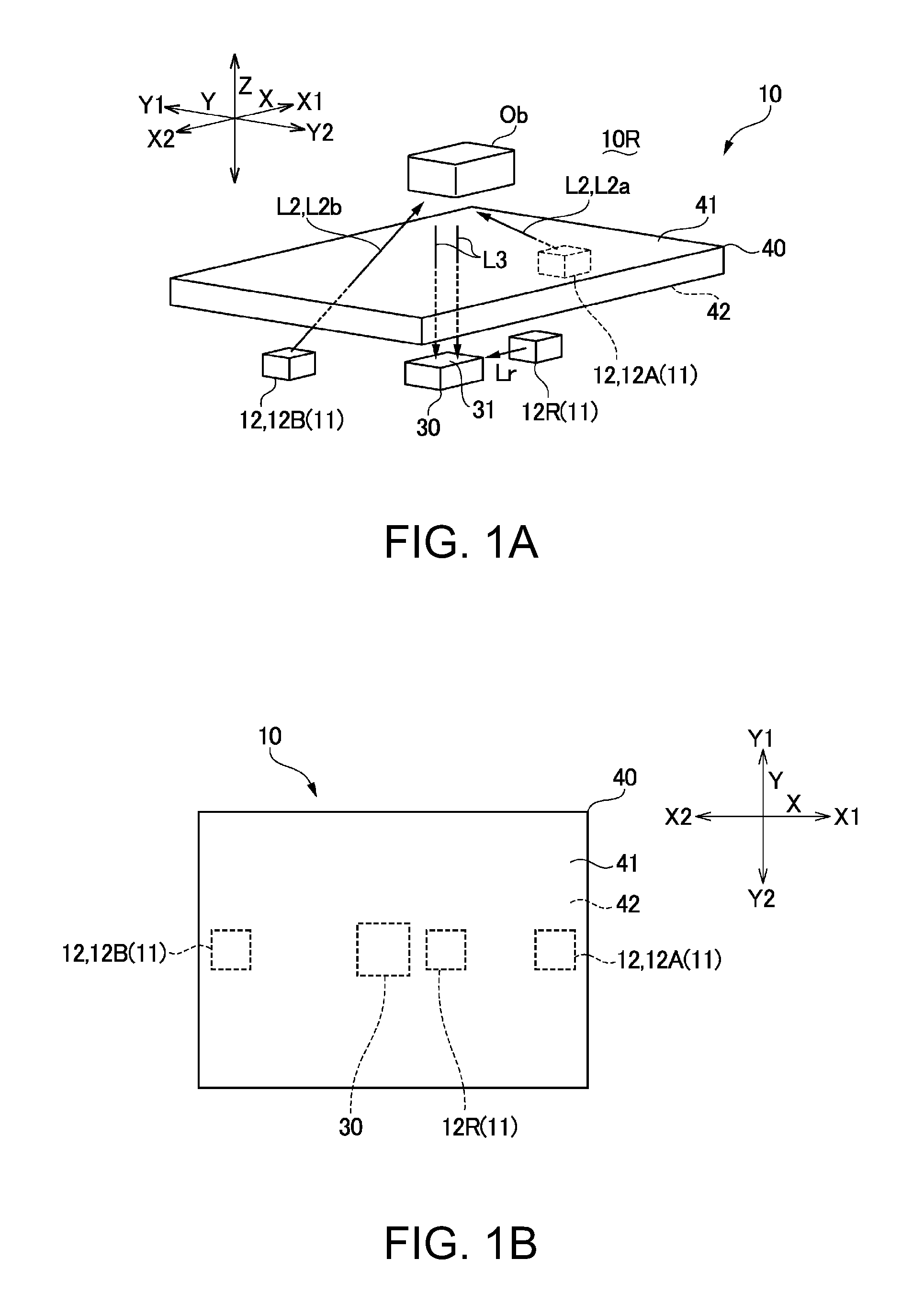
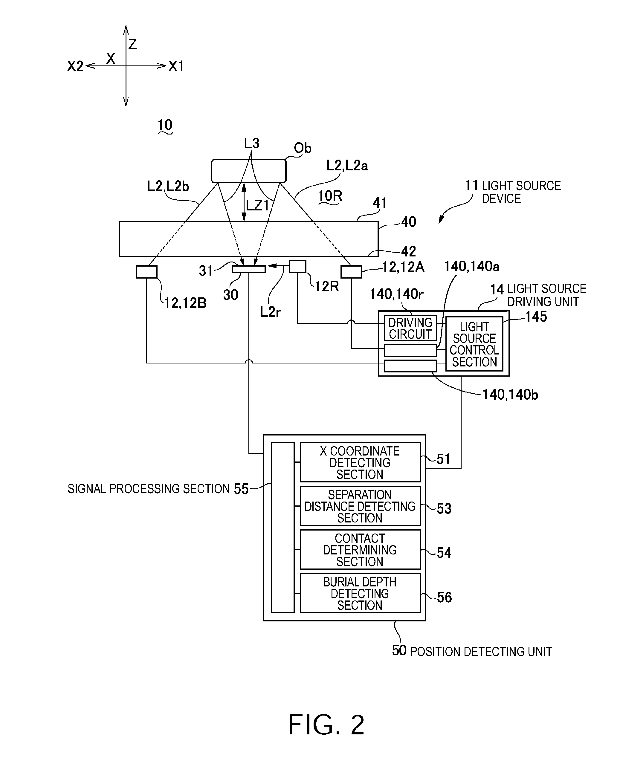
[0033]FIGS. 1A and 1B are explanatory diagrams schematically showing a major portion of an optical-type position detecting device according to Embodiment 1 of the invention. FIG. 1A is an explanatory diagram showing the three-dimensional disposition of constituent elements of the optical-type position detecting device, and FIG. 1B is an explanatory diagram showing the planar disposition of the constituent elements of the optical-type position detecting device. FIG. 2 is an explanatory diagram showing the entire configuration of the optical-type position detecting device according to Embodiment 1 of the invention. FIGS. 3A and 3B are explanatory diagrams schematically showing the state in which a target object is brought into contact with the translucent member and the like in the optical-type position detecting device according to Embodiment 1 of the invention. FIG. 3A is an explanatory diagram schematically showing the state in which the target object is brought...

embodiment 2

[0093]While in Embodiment 1 an example in which the position (the X coordinate) of the target object Ob in the in-plane direction is detected, in addition to the separation distance of the target object Ob from the translucent member 40 and contact between the target object Ob and the translucent member 40, by using the common light detector 30 in the optical-type position detecting device 10 has been described, an example in which the YX coordinates of the target object Ob is further detected will be described with reference to FIGS. 7A to 10D.

Entire Configuration

[0094]FIGS. 7A and 7B are explanatory diagrams schematically showing a major portion of an optical-type position detecting device according to Embodiment 2 of the invention. FIG. 7A is an explanatory diagram showing the three-dimensional disposition of constituent elements of the optical-type position detecting device, and FIG. 7B is an explanatory diagram showing the planar disposition of the constituent elements of the o...


PUM


Abstract

An optical detection device includes: a translucent unit that has elasticity; a light source unit that emits detection light toward the translucent unit; a light sensitive unit that is directed toward the translucent unit and has light sensitivity; and a detection unit that detects a target object based on the intensity of light received by the light sensitive unit.

Description

[0001]This application claims priority to Japanese Patent Application No. 2009-273174 filed Dec. 1, 2009 which is hereby expressly incorporated by reference herein in its entirety.BACKGROUND[0002]1. Technical Field[0003]The present invention relates to an optical-type position detecting device capable of detecting the position of a target object located on one side of a translucent member and a hand apparatus and a touch panel that include the optical-type position detecting device.[0004]2. Related Art[0005]In robotic end effectors such as grippers, hand apparatuses and the like that are mounted on robot arms, optical-type position detecting devices that detect the position of a target object are used. The optical-type position detecting devices are configured to transmit the result of optical detection of a relative position of the target object and a hand as feedback. Generally, devices that use imaging devices have been proposed as such optical-type position detecting devices (se...

Claims


Application Information

Patent Timeline
Patent Type & Authority Applications(United States)
IPC IPC(8): B66C1/42G01B11/14G06F3/041B25J15/08B25J19/04G06F3/033G06F3/0346
CPCG01D5/34715G06F2203/04101G06F3/0425G06F3/042
Inventor NAKANISHI, DAISUKE
Owner COLUMBIA PEAK VENTURES LLC
Why Eureka
Try Eureka