Power supply control apparatus

Inactive Publication Date: 2011-06-02
TOYOTA IND CORP
View PDF5 Cites 29 Cited by
  • Summary
  • Abstract
  • Description
  • Claims
  • Application Information

AI Technical Summary

Benefits of technology

[0004]Accordingly, it is an objective of the present invention to provide a power supply control apparatus that is capable of

Problems solved by technology

However, according to the above prior art, the high voltage battery and the motor cannot be connected each other during the period from when the connection between the high volta

Method used


Image

  • Power supply control apparatus
  • Power supply control apparatus
  • Power supply control apparatus

Examples


Example

[0012]A power supply control apparatus according to a preferred embodiment of the present invention will now be described with reference to the drawings.

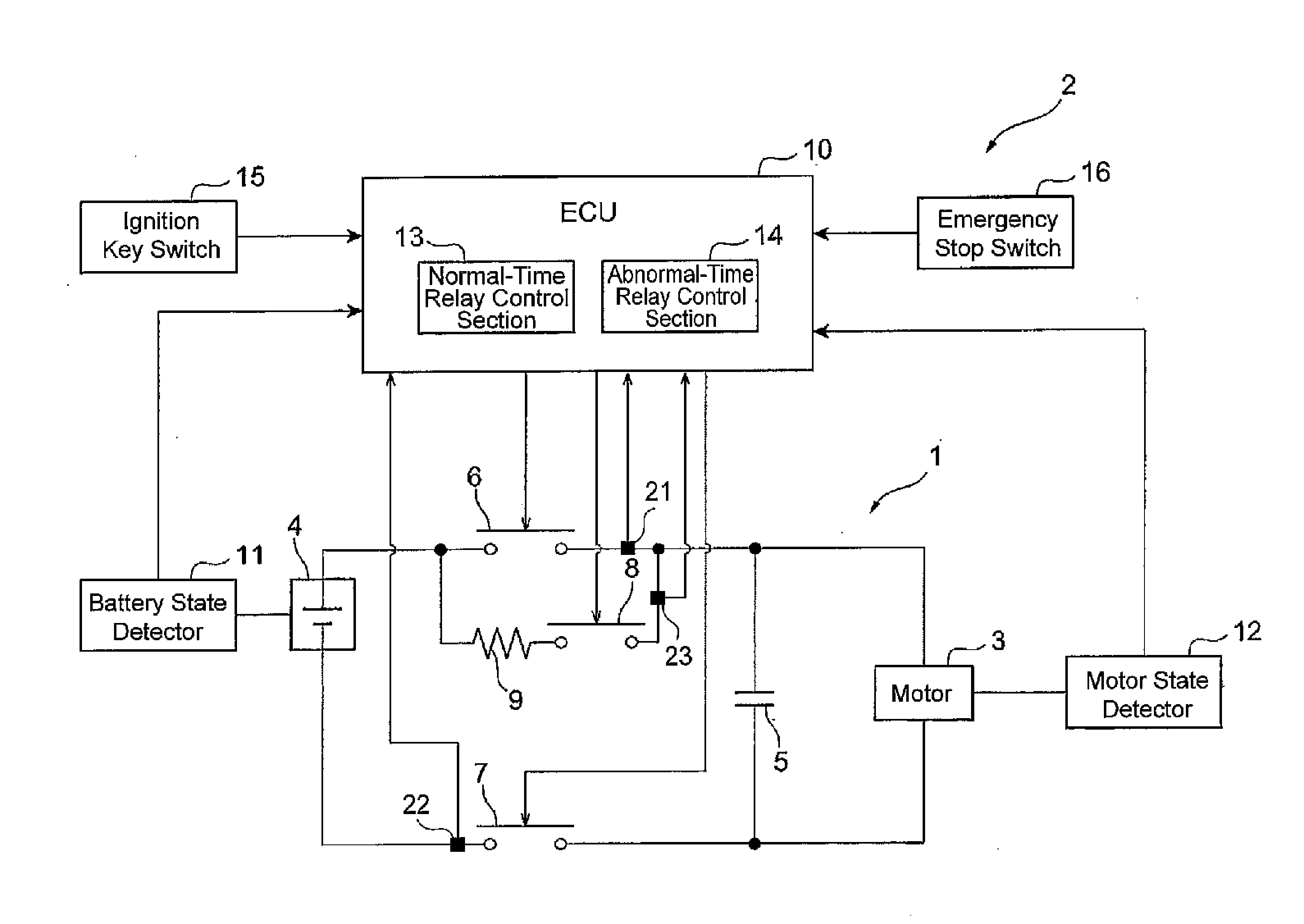
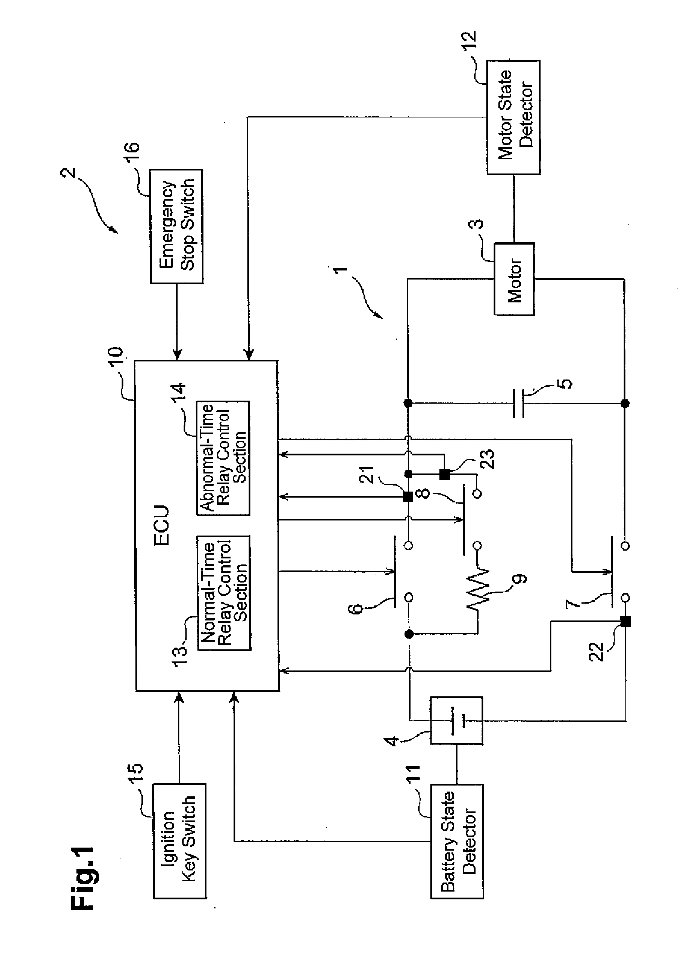
[0013]With reference to FIG. 1, a power supply unit 1 and a power supply control apparatus 2 are mounted on a forklift, which is a type of industrial vehicle.

[0014]The power supply unit 1 includes a motor 3 and a high voltage battery 4 for supplying power to the motor 3. The motor 3 is a drive motor that rotates wheels of the forklift. The high voltage battery 4 is a large capacity battery of, for example, DC 200V. A capacitor 5 for filtering the current through the motor 3 is connected in parallel with the motor 3.

[0015]A main relay 6 is connected between the positive terminal (+) of the high voltage battery 4 and the motor 3, and a ground relay 7 is connected between the negative terminal (−) of the high voltage battery 4 and the motor 3. A pre-charge relay 8 is connected in parallel with the main relay 6.

[0016]An inrush current l...


PUM


Abstract

A power supply control apparatus for controlling a power supply unit including a battery and a load is provided. The power supply control apparatus includes a main relay and a ground relay, a pre-charge relay, an inrush current limiting resistor, a first relay control section, and a time measurement section. The main relay and the ground relay are connected between the battery and the load. The pre-charge relay is connected in parallel with one of the main relay and the ground relay. The inrush current limiting resistor is connected in series with the pre-charge relay, and limits an inrush current from the battery to the load. The first relay control section temporarily turns ON the pre-charge relay and turns ON the main relay and the ground relay upon receiving a power supply connection request from the outside, and turns OFF the main relay and the ground relay upon receiving a power supply interruption request from the outside. The time measurement section chooses a time point in the period from when the pre-charge relay is turned ON to when it is turned OFF, and measures the elapsed time from the chosen time point. Before the elapsed time measured by the time measurement section reaches a predetermined reference period, the first relay control section does not turn OFF the main relay and the ground relay, but maintains the relays ON, even when receiving the power supply interruption request.

Description

BACKGROUND OF THE INVENTION[0001]The present invention relates to a power supply control apparatus for controlling a power supply unit mounted on a vehicle.[0002]Japanese Laid-Open Patent Publication No. 2004-88821 discloses a power supply control apparatus that keeps track of the number of times a motor serving as a vehicle drive source is connected to a high voltage battery for supplying power to the motor. When the count value reaches a predetermined value, the power supply control apparatus inhibits the connection between the high voltage battery and the motor providing time for an inrush current limiting resistor to radiate heat, thereby protecting the resistor.[0003]However, according to the above prior art, the high voltage battery and the motor cannot be connected each other during the period from when the connection between the high voltage battery and the motor is inhibited to when the inrush current limiting resistor has sufficiently radiated heat. This creates a time per...

Claims


Application Information

Patent Timeline
IPC IPC(8): H01H47/00
CPCB60L3/0069B60L3/04F02N11/10F02N11/087F02D2041/2048
Inventor KATO, NORIHIKOKUBOTANI, TAKEHIROKOIDE, YUKIKAZU
Owner TOYOTA IND CORP
Why Eureka
Try Eureka