However, it has been found that the RFID transmission technique is not well suited for sensor transponders since the higher current requirement of such a transponder, the useful broad range of transmission at small dimensions, and possibly existing lossy materials that might surround the transponder set limits to the RFID technique.
Even though several sensor transponders have already been known, their range of transmission is small, so that their application possibilities are limited.
By reference to such a
system, the disadvantages of conventional passive transponders shall be discussed below, said disadvantages occurring, in particular, in environments where the transponder is surrounded by lossy materials, such as human tissue, for example.
So-called passive transponder systems are of particular interest in this context, since the above-mentioned transponders typically remain inside a patient's body for a relatively long period of time, and therefore, conventional power supply by means of a local battery is not possible.
Due to the available transponder dimensions, this is typically not possible at all.
Alternatively, the implanted transponders might be replaced or removed after a predetermined time period and be fitted with new batteries, which is undesirable, however, since this would involve unnecessary interventions for the patients.
Thus, utilization of transponders which have a local battery is not desirable in this field.
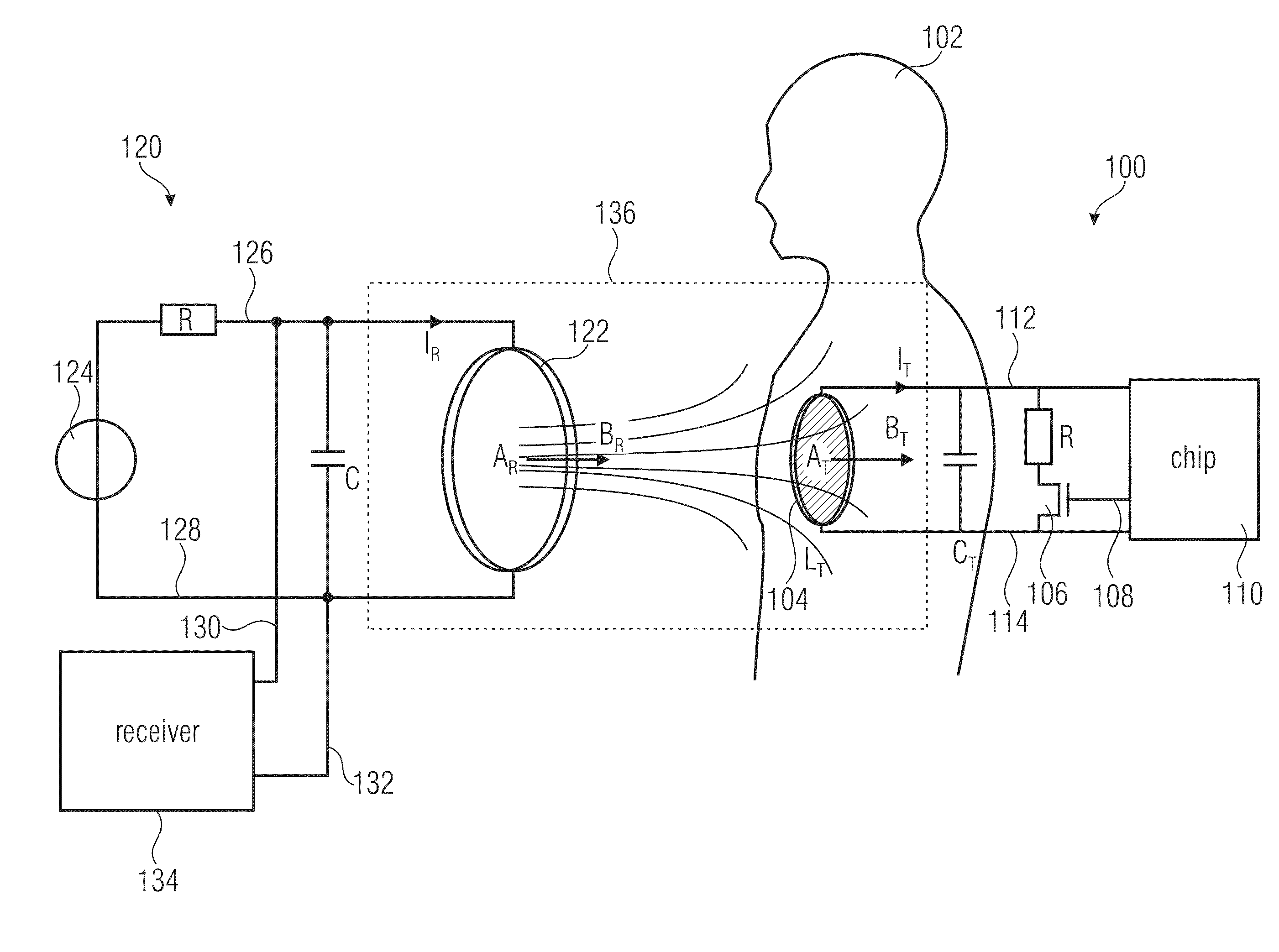
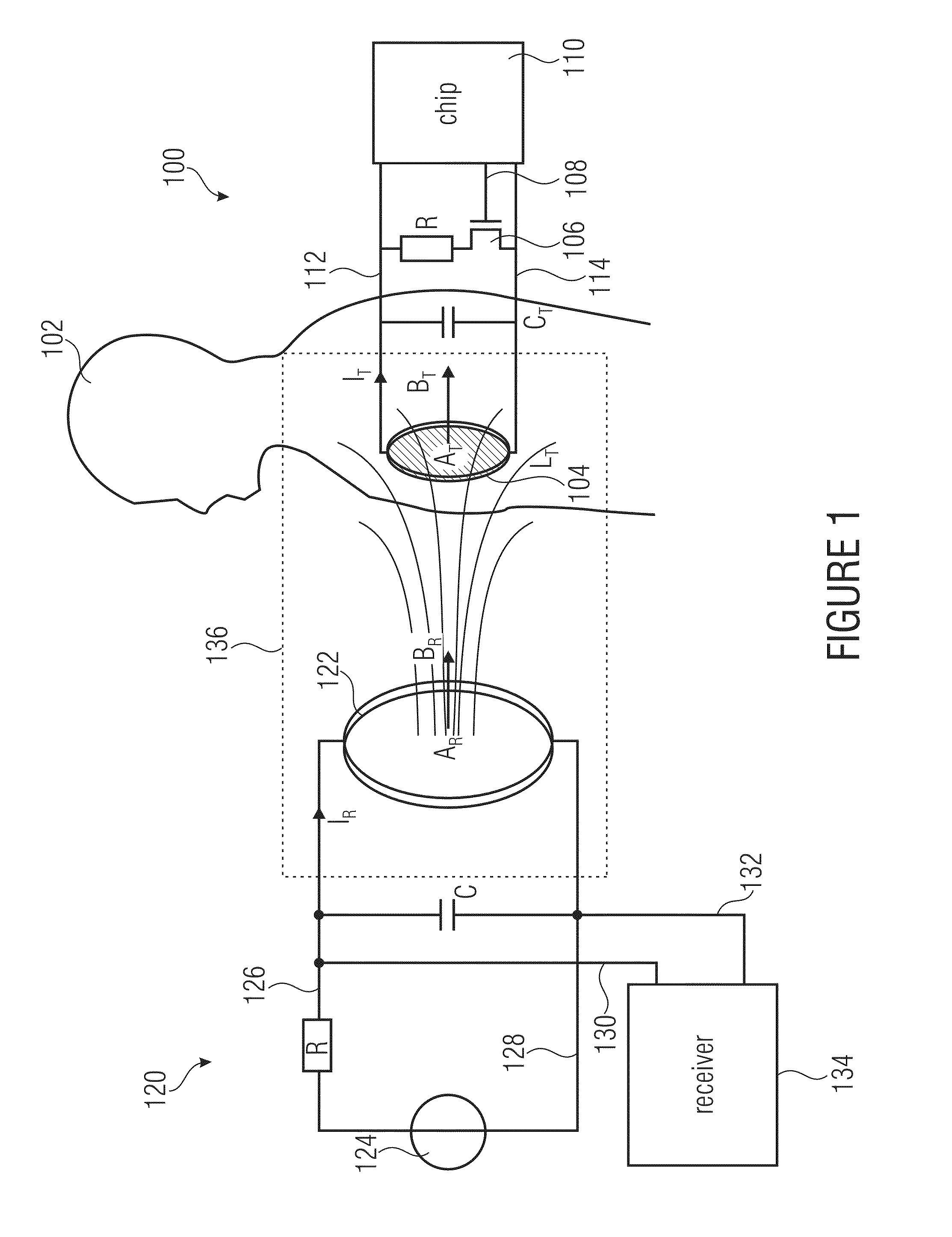
The discussion which follows shows that conventional transponder systems as are shown in FIG. 1 are unsuitable.
The frequencies mentioned represent a fair compromise between loss effects inside a
human body and the antennas; however, said loss effects also increase as frequencies increase.
Also, the
voltage amplitude caused by the generator 124 at the reader antenna 112 is relatively high as compared to the transponder
signal, which also makes
signal processing more difficult.
Furthermore, the
noise of the power
amplifier within the
receiver 134 is more intense than the transponder
signal, so that in the event that the signal /
noise ratio (SNR) may fall below a minimum, decoding of the transponder signal will no longer be possible.
In addition, in such a field of application, the
noise created by the person or patient as well as antenna movements caused by a movement of the patient will also interfere with
data transmission.
The power
amplifier also adds a noise caused by the
shot noise of the pn junctions and by the so-called Johnson noise of the resistors.
In addition to the undesired noise, there is further interference which makes decoding of the transponder signal more difficult, for example a
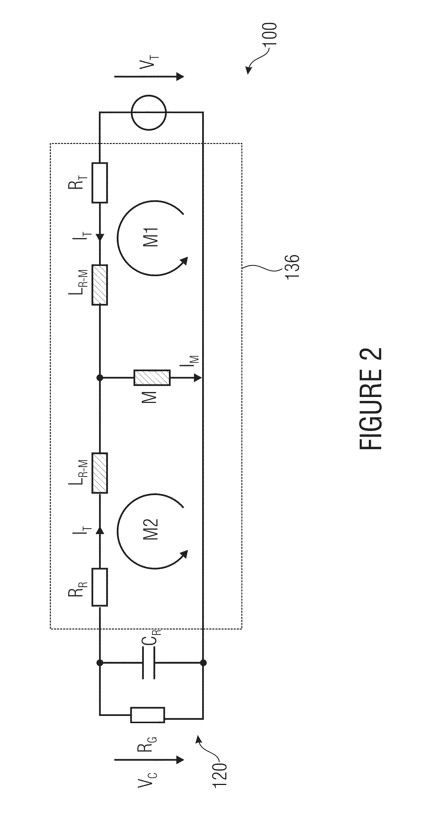
distortion that results from detuning of the reader antenna 112 and that causes a shift, or offset, in the
transfer function within the frequency range.
As a result, the transponder signal is distorted, which makes itself felt by a beat of the transponder signal.
This shows that
data transmission is not possible while using conventional load modulation.
In actual fact, conventional load modulation has several disadvantages, which lead to a considerable reduction of the reading range.
An amplitude variation of the
carrier signal, caused by the detuning or by antenna movements, irreversibly superimposes the
data signal and renders decoding difficult, if not impossible.
In addition, a load modulation wastes energy within the transponder, since during the modulation phase, the modulation
resistor is connected to the resonant circuit, and the energy stored within the resonant circuit is transformed into heat during the modulation phase and therefore cannot be reused.
For this reason it is desirable to increase the
spectral distance between the reader signal and the
data signal; in conventional technology, there are various possibilities of achieving this; however, they do not lead to a useful solution for employing a sensor inside a
human body.
However, this technique is disadvantageous since it still employs load modulation, with all of the above-described disadvantages.
A further problem is the envelope function of the
voltage across the transponder antenna, which limits the possible
frequency shift.
However, this approach has several disadvantages, so that it is not suited for being applied in medical sensor transponders.
Firstly, there is not sufficient room for a second antenna within a transponder that is to be implanted by means of a
catheter.
A second problem is the fact that a useful fixed orientation of the antennas for the implanted transponder is not always guaranteed, and that said implanted transponder also has a very poor
energy balance.
For this purpose, only the power received from the reader by means of the first antenna is available, but losses will occur within the
rectifier and the
amplifier which drives the second antenna.
The efficiency of the
rectifier depends on the threshold voltages of the diodes used and on the parasitic capacitances, so that even when using a highly efficient amplifier for driving the second antenna, such as a class C amplifier, 20% of the power will still be lost.
However, a
disadvantage is the requirement of providing a load
capacitor having sufficient capacity which more clearly exceeds the dimensions admissible for an implantable transponder.
As in the method using orthogonal antennas, losses will also occur within the
rectifier and the amplifier, so that power will be lost.
In addition, data transmission consumes more time since it has to be interrupted periodically to transmit energy.
For continuous
pressure data transmission, higher data rates and a buffer within the transponder would thus be useful, so that this method, too, cannot be employed for the above-mentioned applications.
In summary, one may therefore state that the approaches—described in detail above and known from conventional technology—of using passive transponders are not sufficient for supplying a sensor transponder having a limited antenna size with sufficient energy while ensuring safe data transmission, in particular in environments wherein the transponder is surrounded by attenuating material, such as when being used inside a
human body.



