Check patentability & draft patents in minutes with Patsnap Eureka AI!

Low Chirp Coherent Light Source

a light source and low chirp technology, applied in semiconductor lasers, laser optical resonator construction, laser details, etc., can solve the problem of increasing the linewidth of the emitted coherent light, and achieve the effect of reducing multipath interference intensity, increasing the linewidth, and facilitating injection

Inactive Publication Date: 2011-06-09
EMCORE INC
View PDF16 Cites 24 Cited by
  • Summary
  • Abstract
  • Description
  • Claims
  • Application Information

AI Technical Summary

Benefits of technology

[0009]This and other objects are also provided by a coherent light source having a semiconductor laser resonator and an optical amplifier which amplifies coherent light emitted by the semiconductor laser in response to current injection, in which a heater is provided to modulate the temperature of the semiconductor laser resonator. Such temperature modulation results in a corresponding variation of the laser wavelength, resulting in an increase in the linewidth of the emitted coherent light. This increase in the linewidth reduces multipath interference intensity and undesirable non-linear effects such as SBS.
[0010]This and other objects are further provided by a semiconductor laser having a monolithic gain region, having a first section forming a laser resonator and a second section forming an optical amplifier, and first and second electrodes arranged for injecting current into the first and second sections respectively. This facilitates the injection of a first current into the laser resonator to produce coherent light satisfying a desired chirp requirement, and a second current into the optical amplifier to satisfy an optical power requirement.

Problems solved by technology

Such temperature modulation results in a corresponding variation of the laser wavelength, resulting in an increase in the linewidth of the emitted coherent light.

Method used


Image

  • Low Chirp Coherent Light Source
  • Low Chirp Coherent Light Source
  • Low Chirp Coherent Light Source

Examples


first embodiment

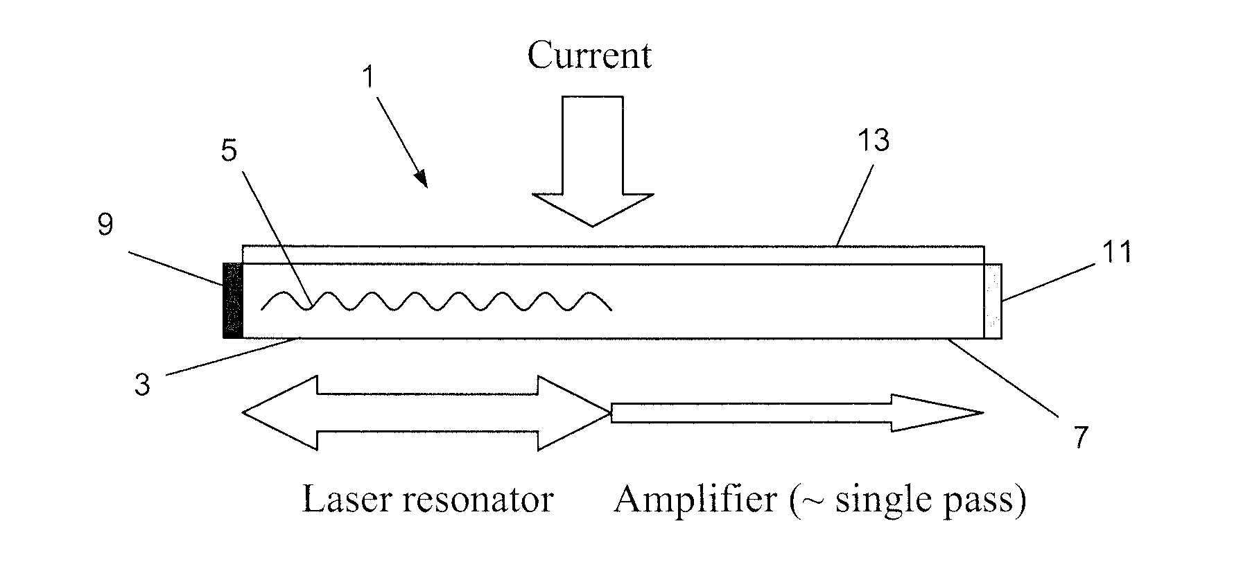
[0020]As shown in FIG. 1, a first embodiment of the invention is formed by a coherent light source 1 having a semiconductor laser resonator 3, including a distributed feedback reflector 5, monolithically integrated with a semiconductor optical amplifier 7. The coherent light source 1 has a ridge (not shown in FIG. 1) formed in a conventional manner to define an elongated waveguide, and a gain region which extends in a conventional manner along the length of the coherent light source 1. The semiconductor laser resonator 3 is formed at one side of the waveguide and the semiconductor optical amplifier 7 is formed at the other side of the waveguide. Coatings are placed at the end of the coherent light source 1 adjacent to the semiconductor laser resonator 3 to form a highly-reflective mirror 9 at the lasing wavelength, while coatings are placed at the end of the coherent light source 1 adjacent to the semiconductor optical amplifier 7 to form an anti-reflection coating 11 at the lasing ...

second embodiment

[0025]While the coherent light source 1 of the first embodiment exhibits low chirp, the reduced linewidth may lead to unwanted interferometric intensity noise and second-order effects such as SBS. As shown in FIG. 6, a second embodiment of the invention is formed by a coherent light source 21 having a resistive heater 23 added to the top of the ridge defining the waveguide. In FIG. 6, features which are the same as corresponding features of the first embodiment have been referenced using the same reference numerals and will not be described in detail again. The resistive heater 23 is electrically insulated from the electrode 13 by a dielectric layer 25.

[0026]In this embodiment, the resistive heater 23 is formed by a layer of Ti / NiCr / Pt. A drive circuit 27 supplies a drive signal to the resistive heater 23 which varies the temperature of the semiconductor laser resonator 3, thereby varying the laser wavelength. In particular, the variation of temperature introduces a thermal chirp ty...

third embodiment

[0027]As discussed above, in the first embodiment a common electrode injects current both into the laser resonator 3 and the optical amplifier 7. As shown in FIG. 7, a third embodiment of the invention is formed by a coherent light source 31 having separate electrodes 33a, 33b respectively associated with the semiconductor laser resonator 3 and the semiconductor optical amplifier 7. In FIG. 7, features which are the same as corresponding features of the first embodiment have been referenced with the same reference numerals and will not be described in detail again.

[0028]Providing separate electrodes 33a, 33b allows greater controllability of the optical properties of the coherent light source 31. In particular, by allowing different currents to be injected into the semiconductor laser resonator 3 and the semiconductor optical amplifier 7, a single device can be used to achieve many different combinations of chirp factor and optical power output. Alternatively, it may be desirable to...


PUM


Abstract

A coherent light source having a semiconductor laser resonator and an optical amplifier which amplifies coherent light emitted by the semiconductor laser resonator in response to current injection, in which the amount of current injected into the semiconductor laser is controlled for conformity with a chirp requirement of an optical communication system. The optical amplifier, which introduces no chirp, may be controlled to match an optical power requirement of the optical communication system. A heater may be provided to introduce a low frequency chirp in order to suppress interferometric intensity noise and unwanted second-order effects such as stimulated Brillouin Scattering. The optical amplifier may be monolithically formed with the semiconductor laser resonator, with separate electrodes provided for injecting current into the semiconductor laser resonator and the optical amplifier.

Description

FIELD OF THE INVENTION[0001]The invention relates to generally a coherent light source having low chirp. The invention has particular, but not exclusive, relevance to light sources for fiber optic communication systems.BACKGROUND OF THE INVENTION[0002]Dispersion management is one of the key techniques for optical fiber communication, for example around the 1.5 micron telecommunications window. Dispersion is caused by optical signals with different wavelengths propagating at different speeds in the optical fiber. Therefore, an original optical pulse having components at multiple optical frequencies will spread while propagating through an optical fiber, resulting in distortion of the optical pulse or smearing of two optical pulses at the time of detection.[0003]A single-mode distributed feedback semiconductor laser has a number of attractive properties as a coherent light source for optical communication, including a very narrow spectral linewidth in the order of 1 Megahertz. Althoug...

Claims


Application Information

Patent Timeline
Patent Type & Authority Applications(United States)
IPC IPC(8): H01S5/026H01S5/12
CPCH01S5/0261H01S5/0265H01S5/20H01S5/06251H01S5/12H01S5/0612
Inventor SU, HUIZHANG, GENZAOBLAUVELT, HENRY A.
Owner EMCORE INC
Features
  • R&D
  • Intellectual Property
  • Life Sciences
  • Materials
  • Tech Scout
  • Unparalleled Data Quality
  • Higher Quality Content
  • 60% Fewer Hallucinations
Learn More