Saddle Faced Small Animal Sensor Clip

a sensor clip and saddle face technology, applied in the field of non-invasive photoplethysmographic sensor clips, can solve the problems of affecting the accuracy of the image, so as to prevent the clip from relocating over time, facilitate the alignment, and prevent the effect of tissue contusion

Inactive Publication Date: 2011-06-09
STARR LIFE SCI
View PDF14 Cites 6 Cited by
  • Summary
  • Abstract
  • Description
  • Claims
  • Application Information

AI Technical Summary

Benefits of technology

[0032]The shorter opposed distal end side (measured longitudinally from the sensor position) of this saddle shape facilitates the ability to align the transmitted and received light with the bone, while the overall saddle shape of the facing provides a physical grip to capture enough tissue to prevent the clip from relocating over time while it is attached to the limb.
[0033]The shorter (depth-wise or height wise) hinge end side also allows the clip to close when it is fully assembled. The edges of the projections at the ends of the saddle shaped clip are preferably rounded off to prevent the contusions of the tissue that may result from long-term contact.

Problems solved by technology

Any such clip movement would likely cause a slow degradation of the quality of the light signals over the duration of a continuous measurement and typically cause an interruption in the usable data that is obtained.
The second problem is that in a system where the intensity of the input light is low, as is the case with magnetic resonance imaging (MRI) measurements using fiber optic cables, which inherently significantly attenuate the input and received light, position of the sensor is more critical to obtaining good signals for measurement.
Under low input light, it can take a researcher significant time to find a clip placement location where sufficient received light intensity exists to make quality measurements.

Method used


Image

  • Saddle Faced Small Animal Sensor Clip
  • Saddle Faced Small Animal Sensor Clip

Examples


Embodiment Construction

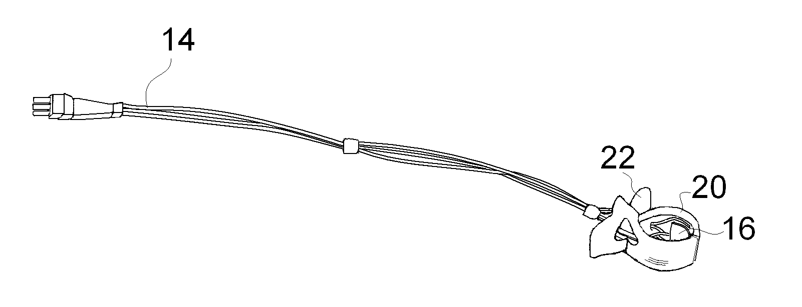
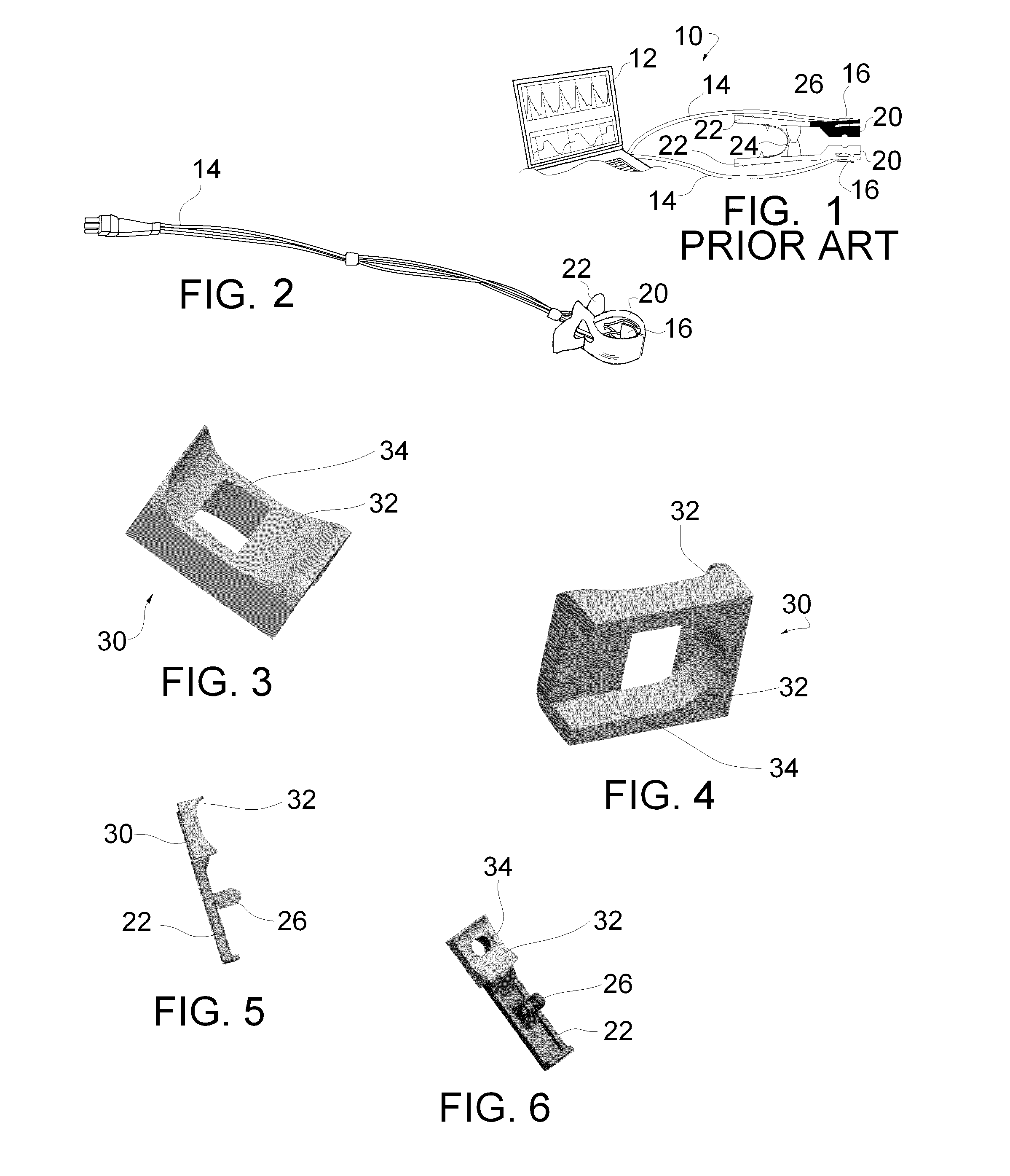
[0044]In summary, the present invention relates to a noninvasive photoplethysmographic sensor platform 10, namely a sensor clip, for small animals, such as rats and mice that are typically utilized in a laboratory environment. The platform generally is operable on a computer or controller 12 with a display such as a lap top. The controller 12 may also include signal processing elements such as an external signal processing box. Cables 14 extend from the controller 12 to sensors 16 held within the animal engaging end 20 of a clip. The clip includes gripping elements 22, a biasing spring 24 and a pivot connection 26. Photoplethysmographic measurements on laboratory animals have most often been accomplished on restrained and / or anesthetized animals. Further, in the pulse oximetry field there has been a lack of adequate photoplethysmographic sensors for small mice (and even small rats), until the advent of the Mouse Ox™ brand pulse oximeters by Starr Life Sciences.

[0045]FIG. 1 is a sche...


PUM


Abstract

A noninvasive photoplethysmographic sensor platform for small animals provides a spring biased sensor clip, wherein at least one side of the sensor clip is provided with a saddle faced clip face member. The saddle shape of the clip face member may have a hinge end, toward the hinge of the clip, which is longer in the longitudinal direction of the clip and shorter in depth than the distal end. The shorter distal end side (measured longitudinally) of this saddle shape facilitates the ability to align the transmitted and received light with the bone, while the overall saddle shape of the facing provides a physical grip to capture enough tissue to prevent the clip from relocating over time while it is attached to the limb. The shorter hinge end side (depth-wise) also allows the clip to close when it is fully assembled. The edges of the saddle shaped clip are preferably rounded off to prevent the contusions of the tissue that may result from long-term contact. This saddle faced feature works well on only one side of the clip.

Description

[0001]The present invention claims priority of U.S. Provisional Patent Application Ser. No. 61 / 180,161 entitled “Saddle Faced Small Animal Sensor Clip”.BACKGROUND OF THE INVENTION[0002]1. Field of the Invention[0003]The present invention relates to photoplethysmographic readings for animal research and more particularly, the present invention is directed to a noninvasive photoplethysmographic sensor clip designed for improving the sensor position to maximize the usable signal.[0004]2. Background Information[0005]Photoplethysmography[0006]A photoplethysmograph is an optically obtained plethysmograph, which, generically, is a measurement of changes in volume within an organ whole body, usually resulting from fluctuations in the amount of blood or air that the organ contains. A photoplethysmograph is often obtained by using a pulse oximeter.[0007]A conventional pulse oximeter monitors the perfusion of blood to the dermis and subcutaneous tissue. Pulse oximetry is a non invasive method ...

Claims


Application Information

Patent Timeline
Patent Type & Authority Applications(United States)
IPC IPC(8): A61B5/02A61B5/00
CPCA61B5/14552A61B2503/40A61B5/6826
Inventor HETE, BERNARD F.STARR, ERIC W.
Owner STARR LIFE SCI
Why Eureka
Try Eureka